I believe the 753 is the Philips version of the Marantz 5000, the 751 is the Philips version of the CD48. All use the 1549
There's also a Sugden that uses the 1549 - CD21 I think.
Regards
Pete
The Sugden looks rather nice too - much better board and layout - I'd have liked one of those to wreck....hahahaha
Pete...I'm going to prep the player to accept the last traff this weekend and basically copy your idea of powering the main board.
I'm wiring the new traff as 9v - 0 - 9v and I guess it's just a snip and strip of the original white / green / white tx wires and just attach to the new traff ?
I've read the service manual 76 times ( lol ) and viewed your pics even more than that so I'm reasonably confident.
I've also ran out of transformer fixing hardware so I'm going to just make a sort of retaining bar to hold it firmly in place temporarily.
It'll be bolted on the outside of the case alongside the original little tx.
Not very elegant but it's a short term thing while my new design takes shape.
The idea is actually proving to be just as interesting to sort out as I look at different ways of isolating the main board and clock from external vibration and likewise the electro radiation of all these transformers.
I'll also be isolating the optical unit and what remains of the transport plastics too - it's a lot of fun drawing daft pictures and measuring stuff to aid positioning of all the bits.
I'm considering those screened cans over each traff, copper sheet under the green board and that very squashy and sticky black material that is available in sheet form and pre made domed anti vibration feet for under amps and record players.
What's that called again ?
I'll remember later.
If there's a sonic benefit to all this bugg....ing around that'll be a bonus.
The main thing is to have something that looks half presentable - just like it isn't right now !!
Last edited:
I'm wiring the new traff as 9v - 0 - 9v and I guess it's just a snip and strip of the original white / green / white tx wires and just attach to the new traff ?
The main thing is to have something that looks half presentable - just like it isn't right now !!
Keep the original green connected as well as the earth for the new tx. the original green is needed for ground on the part of the original tx that you're still using (I think).
I always think the point of the original cover is to keep the the player looking neat (irrespective of how bodged the inside is) 🙂
Regards
Pete
Blimey - thanks for that !
So....you mean connect the centre green of the small tx to the new 'o' volt of my new transformer too ?
Then feed the main board with it and the 2x 9v feeds ?
If that's the case I would never have done it or even thought about it....
The stuff I could not remember is ' Sorbothane '
So....you mean connect the centre green of the small tx to the new 'o' volt of my new transformer too ?
Then feed the main board with it and the 2x 9v feeds ?
Yes, that's the way I did it
Here is another route...just for cherry picking
Hi all,
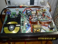
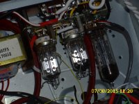
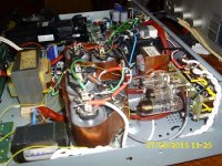
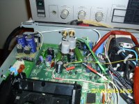
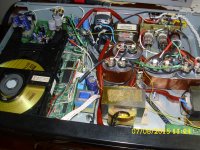
very interesting thread...I just submit another route to go. Very breifly, mains AC filter, and then general regulation with LM 350 & LM 333 for all digital parts , including mechanism, followed with 3 independent 5 volt regs (for decoder , drive chip and all other). Then the big challenge. The analog supply is consisted from 3 tube rectifiers. 2* 6AL5 conforming a bridge for the buffer opamp and 1 * 6X4 for the DAC supply, followed of one 5V regulator. Buffer opamp is replaced by my beloved AD8066 coupled with 600ohm line otput transformers.
Tubes in power supply just enter the project to a new universe. I can't describe the speed , the timing, the aliveness and the flow of music. The already analog tone of the player is reinforced by a great margin by removing all edges in mid and high frequencies. But the bigger success is on the bass definition which becomes absolutely chord sound. Be aware!! There is still remaining the issue of not very deep soundstage -flat image, compared with other players as Rotels and marantz 1541's based. I will give a try by disengaging the internal I/V conv in DAC and replace it with an external one, that I suspect it is the route of problem. Cheers to all !!
Hi all,
very interesting thread...I just submit another route to go. Very breifly, mains AC filter, and then general regulation with LM 350 & LM 333 for all digital parts , including mechanism, followed with 3 independent 5 volt regs (for decoder , drive chip and all other). Then the big challenge. The analog supply is consisted from 3 tube rectifiers. 2* 6AL5 conforming a bridge for the buffer opamp and 1 * 6X4 for the DAC supply, followed of one 5V regulator. Buffer opamp is replaced by my beloved AD8066 coupled with 600ohm line otput transformers.
Tubes in power supply just enter the project to a new universe. I can't describe the speed , the timing, the aliveness and the flow of music. The already analog tone of the player is reinforced by a great margin by removing all edges in mid and high frequencies. But the bigger success is on the bass definition which becomes absolutely chord sound. Be aware!! There is still remaining the issue of not very deep soundstage -flat image, compared with other players as Rotels and marantz 1541's based. I will give a try by disengaging the internal I/V conv in DAC and replace it with an external one, that I suspect it is the route of problem. Cheers to all !!
Attachments
-
 Optimized-DSCI0611.JPG879.4 KB · Views: 356
 -
 Optimized-DSCI0619.JPG812.1 KB · Views: 207
 -
 Optimized-DSCI0617.JPG737.5 KB · Views: 219
 -
 Optimized-DSCI0616.JPG817.9 KB · Views: 207
 -
 Optimized-DSCI0615.JPG898.4 KB · Views: 330
 -
 Optimized-DSCI0614.JPG889.3 KB · Views: 330
 -
 Optimized-DSCI0613.JPG973.1 KB · Views: 343
 -
 Optimized-DSCI0612.JPG918.9 KB · Views: 347
OMG......don't know what to say !!!!
That is truly astonishing.....I need to ask some questions but I don't know which one to ask first !!!!!!
How do you power decoder , drive chip and all others ?
I've wanted to do that for a while.
Can you explain it ?
I'm tired of reading the service manual to look for a way.
Thanks for joining in - I'm sure Pete will be interested too ...
Still can't believe your work - it's just fantastic
Hi Andrew,
this is quite easy, as you'd already disassembled the main PCb , several times , I guess.. 🙂
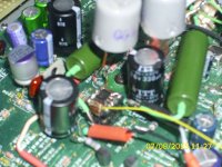
There are already placed specific junctions which transfer the unique 5V DC line. By removing them you can apply the regulators very close to the chips and power them by wire from the main supply source. The reg for the drive chip(TDA 1301) has been placed on components side. The reg for the decoder (SAA7345GP) to solder side. Finally, the original factory 5V regulator feeds all other 5V reference requirements (powerless). The most important is that all of them are a second stage regulation, right after LM 350 with double smoothing capacitors and choke filtering. The next few days I will give a try to the I/V external mode , so as, I 'll have the chance to take some pics and post'em.
Cheers
Andreas
Follow
this is quite easy, as you'd already disassembled the main PCb , several times , I guess.. 🙂
There are already placed specific junctions which transfer the unique 5V DC line. By removing them you can apply the regulators very close to the chips and power them by wire from the main supply source. The reg for the drive chip(TDA 1301) has been placed on components side. The reg for the decoder (SAA7345GP) to solder side. Finally, the original factory 5V regulator feeds all other 5V reference requirements (powerless). The most important is that all of them are a second stage regulation, right after LM 350 with double smoothing capacitors and choke filtering. The next few days I will give a try to the I/V external mode , so as, I 'll have the chance to take some pics and post'em.
Cheers
Andreas
Follow
OMG......don't know what to say !!!!
That is truly astonishing.....I need to ask some questions but I don't know which one to ask first !!!!!!
How do you power decoder , drive chip and all others ?
I've wanted to do that for a while.
Can you explain it ?
I'm tired of reading the service manual to look for a way.
Thanks for joining in - I'm sure Pete will be interested too ...
Still can't believe your work - it's just fantastic
Hi Andrew,
this is quite easy, as you'd already disassembled the main PCb , several times , I guess.. 🙂
There are already placed specific junctions which transfer the unique 5V DC line. By removing them you can apply the regulators very close to the chips and power them by wire from the main supply source. The reg for the drive chip(TDA 1301) has been placed on components side. The reg for the decoder (SAA7345GP) to solder side. Finally, the original factory 5V regulator feeds all other 5V reference requirements (powerless). The most important is that all of them are a second stage regulation, right after LM 350 with double smoothing capacitors and choke filtering. The next few days I will give a try to the I/V external mode , so as, I 'll have the chance to take some pics and post'em.
Cheers
Andreas
Follow
Hi Andreas
Will we see from your pics where the 5v feeds are connected to 1301 and 7345 and which bits are removed or lifted to do this ?
Do you think that external i/v will improve things so much and isn't it a bit dangerous now in view of your already excellent results ?
I guess I've gone for brute force and overkill with my transformer plans and finally a nice clock to clean up some jitter to finish the project off.
If you can show me how I would certainly like to power the other chips - I have the spare power now !!!
Looking forward to your i/v results......
Cheers also
Andrew
Hi Andrew, I'll do my best taking close pics both sides the pcb. I'll also check the numbers of junctions removed to identify them.
Now to the intrigue part. I suspect that internal I/V is a compromise. Although setup does have a distinct musical flavor, there's an "all in the front" behavior and a short of rounding. I' ll try to place another AD8066 which is ideal for such I/V use (fet inputs, ultra wide bandwidth & extremely high slew rate) . The hint to isolate the internal I/V and the regarding feedback resistor is explained in a previous thread , probably remember, low impedance path using a 5532...tricky & risky...
At least , if finally turns on , I'll be sure that all of the potential of CDM12 and 1549 is exploited.
http://www.diyaudio.com/forums/digital-source/189156-tda1305-tda1549-bypass-opamps-2.HTML
I set a quote to HBC , but haven't got a reply yet .
cheers
Andreas
Hi Andreas
Will we see from your pics where the 5v feeds are connected to 1301 and 7345 and which bits are removed or lifted to do this ?
Do you think that external i/v will improve things so much and isn't it a bit dangerous now in view of your already excellent results ?
I guess I've gone for brute force and overkill with my transformer plans and finally a nice clock to clean up some jitter to finish the project off.
If you can show me how I would certainly like to power the other chips - I have the spare power now !!!
Looking forward to your i/v results......
Cheers also
Andrew
I remember well the moment I first removed the awful dual op amp completely and took the signal from the dac legs.
The forward balance changed a lot and then changing the green board main caps brought up the bass levels.
Now with my transformers and regulators for the dac chip I have a sense of large scale and real depth.
There is still some grain in the high frequencies still which I find unpleasant at high volume levels which I'd like to remove.
I'm hoping that a good independently powered clock will fix some of this.
I also suspect that noise on the main 5v rail is polluted by all the chips that share it plus the motor and display all talking to each other.
The chance to just get the SAA7345 out of that chain interests me very much and will be key to another step in quality I'm sure.
My Arcam tda based player had the 7310, ram chips, 7220, Clock and the 1541 all independently powered by their own transformers, bridges, capacitors and regulators. 6 in total ( I love transformers ! ) and it never suffered with any of the issues I have today.
My player still sounds fantastic in the sense that I now have a huge sound stage, tremendous resolution and big impact on bass and mids. HF is beautifully detailed with the very small details that were in the background now easily identified.
The music flows effortlessly too - like my 1541a
The new transparency however exposes things that are not wanted too.
I just don't know whether it's jitter related or distortion...I can't recognise that with my just ears of course !!
I'm hoping that the clock will clean it up a little but isolation of the important chips has to be my ultimate conclusion to a very enjoyable, fun and worthwhile project.
I really hope you get a good result with your very serious surgery - I can only guess how it sounds already !
If you can make it work well I'm sure it will start something new and the price of our machines will go up on E Bay...😱
Best of luck
Andrew
Thanks Andrew for your kind commends!!
Just to raise a concern regarding that you called "grain" in highs. Have you tried any LC choke filters to power supply rails? If not it might help to suppress unwanted ultrasonic noise. In the case you attempt LC filter before the regulator stage, just remember to add a small resistor from 1-3 ohms for impedance compliance.
Chears Andreas
I remember well the moment I first removed the awful dual op amp completely and took the signal from the dac legs.
The forward balance changed a lot and then changing the green board main caps brought up the bass levels.
Now with my transformers and regulators for the dac chip I have a sense of large scale and real depth.
There is still some grain in the high frequencies still which I find unpleasant at high volume levels which I'd like to remove.
I'm hoping that a good independently powered clock will fix some of this.
I also suspect that noise on the main 5v rail is polluted by all the chips that share it plus the motor and display all talking to each other.
The chance to just get the SAA7345 out of that chain interests me very much and will be key to another step in quality I'm sure.
My Arcam tda based player had the 7310, ram chips, 7220, Clock and the 1541 all independently powered by their own transformers, bridges, capacitors and regulators. 6 in total ( I love transformers ! ) and it never suffered with any of the issues I have today.
My player still sounds fantastic in the sense that I now have a huge sound stage, tremendous resolution and big impact on bass and mids. HF is beautifully detailed with the very small details that were in the background now easily identified.
The music flows effortlessly too - like my 1541a
The new transparency however exposes things that are not wanted too.
I just don't know whether it's jitter related or distortion...I can't recognise that with my just ears of course !!
I'm hoping that the clock will clean it up a little but isolation of the important chips has to be my ultimate conclusion to a very enjoyable, fun and worthwhile project.
I really hope you get a good result with your very serious surgery - I can only guess how it sounds already !
If you can make it work well I'm sure it will start something new and the price of our machines will go up on E Bay...😱
Best of luck
Andrew
Thanks Andrew for your kind commends!!
Just to raise a concern regarding that you called "grain" in highs. Have you tried any LC choke filters to power supply rails? If not it might help to suppress unwanted ultrasonic noise. In the case you attempt LC filter before the regulator stage, just remember to add a small resistor from 1-3 ohms for impedance compliance.
Chears Andreas
Never thought of this and actually never included LC in my projects.
Would a 10uh inductor be Ok ?
I'm guessing I need another cap after the main smoothing cap and connect the inductor between the two positives and the resistor across + and -ve rails of the new capacitor ?
Is that it ?
Excuse my ignorance....😱
50uH to 100uH will be ok. This one followed by a decoupling cap, as in your schematic, creates a pole filtering ultra sonic frequencies. There are tons of web simulators where you can calculate your pole frequency. A typical C2 cap value is 47uF. The resistance is in series with the choke to provide good termination impedance to the regulator. A typical value between 1-3 ohm make a good job
Like this.....and a resistor across C2 ?
Attachments
Thanks Andreas - I'll give it a go, seems simple enough.
I've fitted my last 100va to the green board tonight just to try it out - now the poor little original tx is relegated to display duties only.
No more of this insane ' VA adding ' till the diy platform is done.
Then the clock will get one and that's it.
Gains are audible but it's a bit like more of the same - more oomph but no extra finesse.
I suppose I've become familiar with the weight, drive, scale and sheer power which was seriously lacking with the player as standard - in fact there was none of that at the start of all this.
What I'm really chasing is total fluidity, grace and effortless delivery across the audible range - my audible range anyway.
I'm still convinced it's jitter related ( and I'm not saying I can hear jitter btw ) but the clock will deal with some of this stuff I'm not happy with.
What I will say is that Andreas idea of powering the ' saa ' chip and maybe the 1301's independently may sort it out properly too.
I must now admit however 😱 that a ' tricked out ' tda1541a / 7220 / 7310 does something that makes edges of instruments, percussion and metal instruments in particular sound more metallic, glassy, sharp and which flow like running water.
That was hard to admit btw......
The truth then :
In current form my player whacks like a BIG badge Naim CD Player, thumps like the Krell I borrowed for months but sadly lacks some finesse in mids and the higher frequencies.
In my head there's three things left to do...and they'd better work
Clock and only 2 more regulators......
Sure...🙄
Last edited:
Hi Andrew, I'm close to finalize the small plug and play board with the buffered circuit to neutralize the internal DAC I/v, including also the external I/V converter. I will post some pics later today. If everything goes well with power on tests , then tomorrow I am going to disassemble the main PCb to install it. Dont't worry I have in mind to take some pics the decoder & servo regulators and wright down the trace junctions.
If you're behind some big audible changes just go for a tube rectifier. In your case you will need only one full wave tube (eg. 6X4 or EZ81) to feed your DAC only. Just assure that you have available an AC voltage of 28-30 V not center tap and somehow an 6,3 VAC @ 600 mA for the tube filament. At no load this PS will provide almost 40 VDC and under DAC load about 15 VDC, preety convenient to supply your regulators.. So , no electrocution risk 🙂
Anyway, It worths the trouble !!
By the way looking at your pictures, did you removed the feedback capacitors of the internal DAC opamp? 2300/2301 ---> 470 pF
QUOTE=AndrewGM;4387146]Thanks Andreas - I'll give it a go, seems simple enough.
I've fitted my last 100va to the green board tonight just to try it out - now the poor little original tx is relegated to display duties only.
No more of this insane ' VA adding ' till the diy platform is done.
Then the clock will get one and that's it.
Gains are audible but it's a bit like more of the same - more oomph but no extra finesse.
I suppose I've become familiar with the weight, drive, scale and sheer power which was seriously lacking with the player as standard - in fact there was none of that at the start of all this.
What I'm really chasing is total fluidity, grace and effortless delivery across the audible range - my audible range anyway.
I'm still convinced it's jitter related ( and I'm not saying I can hear jitter btw ) but the clock will deal with some of this stuff I'm not happy with.
What I will say is that Andreas idea of powering the ' saa ' chip and maybe the 1301's independently may sort it out properly too.
I must now admit however 😱 that a ' tricked out ' tda1541a / 7220 / 7310 does something that makes edges of instruments, percussion and metal instruments in particular sound more metallic, glassy, sharp and which flow like running water.
That was hard to admit btw......
The truth then :
In current form my player whacks like a BIG badge Naim CD Player, thumps like the Krell I borrowed for months but sadly lacks some finesse in mids and the higher frequencies.
In my head there's three things left to do...and they'd better work
Clock and only 2 more regulators......
Sure...🙄[/QUOTE]
Hi Andreas
' By the way looking at your pictures, did you removed the feedback capacitors of the internal DAC opamp? 2300/2301 ---> 470 pF '
What will this do ?
Can it change the sound in some way ?
I'll look at the service manual again and check this.
On the tube rectifier idea....I've not the confidence to do another valve project.
My 2 x 6N6P buffer works, is very nice sounding but was the most frightening thing I ever made - I don't really want to try something else using tubes
Hi Andreas
Yes, 2300 and 2301 are gone.
I inserted my wires directly from pin 4 and 7 - where 2300 and 2301 caps were.
Should I insert caps back in there and take the signal from them to the coupling caps ?
I'm currently using 10uf caps to the rca sockets - is this too much ?
I have some Clarity caps of 2.2 uf which I'm tempted to try out.......good idea ?
Andrew
Last edited:
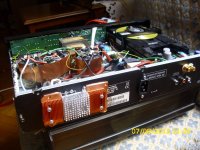
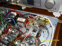
Here's a pic of the last traff job.
I know it's a mess but it won't be like this much longer believe me.
So we're at 5 transformers now and well over 400 VA - it's more than enough...haha
I've also just changed the ' el cheapo ' 10uf output coupling caps to some slightly nicer Clarity Caps @ 2.2 uf.
It's not transformed the sound but has actually changed it quite a bit - it's also improved some of the things I was complaining about in a previous post and I have absolutely no idea why ?
Can a reduction in uf do this or is it in the cap quality ?
Not exactly Audionote etc but this change is really quite noticeable in leading edges, metallic sounds.
No loss in bass depth either so it's a real win.
Maybe I should start saving for some more serious quality caps if this is what happens - very pleased with this
Attachments

Last edited:
- Home
- Source & Line
- Digital Source
- TDA1549 - Marantz CD48