Yes, it sure does 😀
I'd like to offer both, but first off I think i'll supply the blank PCBs first. Then once I get time offer populated and tested PCBs.
I'd like to offer both, but first off I think i'll supply the blank PCBs first. Then once I get time offer populated and tested PCBs.
...just more spectrum analysis pics
Hi Guys,
Just a couple more pics to share.
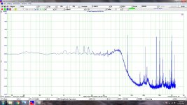
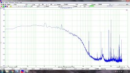
Tonight I thought i'd try powering the 1541 PSU with a switch mode power supply (Gophert CPS-3205) to compare the noise difference with the SLA batteries as I used previously. Looks like the switch mode is quieter... Didn't expect that! Looks like roughly 5.6uV / -105dBV compared to ~ 6.3uV / -104dBV - If i've done the correct calculations.
I've also attached the +5V digital supply noise spectrum analysis. Around -100dBV / 10uV.
All measurements were taken in circuit under load while playing music.
Also, these measurements were taken with 5 point averaging, the high frequency noise may be irrelevant. All I had to do was put my hand on the USB measuring device to completely change the spread of noise in the HF (+100k). I'm weary of the accuracy of the VT DSO-2815H, I think these measurements should be taken as an indication only.
Cheers
Hi Guys,
Just a couple more pics to share.
Tonight I thought i'd try powering the 1541 PSU with a switch mode power supply (Gophert CPS-3205) to compare the noise difference with the SLA batteries as I used previously. Looks like the switch mode is quieter... Didn't expect that! Looks like roughly 5.6uV / -105dBV compared to ~ 6.3uV / -104dBV - If i've done the correct calculations.
I've also attached the +5V digital supply noise spectrum analysis. Around -100dBV / 10uV.
All measurements were taken in circuit under load while playing music.
Also, these measurements were taken with 5 point averaging, the high frequency noise may be irrelevant. All I had to do was put my hand on the USB measuring device to completely change the spread of noise in the HF (+100k). I'm weary of the accuracy of the VT DSO-2815H, I think these measurements should be taken as an indication only.
Cheers
Attachments
Last edited:


Diode attenuator revisit.
Hi All,
I'm slowly but surely getting through all the testing and fine tuning on my pcb.
The Diode attenuators were revisited and evaluated.
Test setup:
Probes set to 10X
LE - Diode attenuation (1V - 2V swing)
DR, DL, BCK resistive attenuation (1V - 2V swing)
Refer to picture attached.
Comparison videos:
LE diode attenuator for TDA1541A
LE no attenuation
Resistive attenuator for LE was also evaluated and found to perform poorly.
My preference for attenuation of LE in simultaneous mode:
1. Diode attenuator
2. No attenuation
3. Resistive attenuation
I'm not sure how well the comparison videos will show the sound difference given the quality of my smartphone, but to my ears its a clear winner.
Ryan
Attachments
Update.
Hi All,
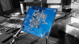
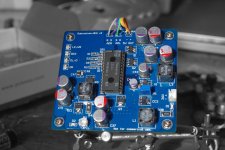
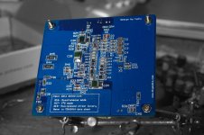
Attached is a picture of my latest prototype (hopefully the last).
This one is for a friend, if all tests well.
PCB features:
-4 layer design.
-Rubycon PMLCAPS.
- 22uF unity gain cap for shunt regs.
- 2.2uF MSB (pins 13, 18).
- 1.5uF (pins 12, 11, 10, 19, 20, 21).
- 100nF C0G/NP0 (pins 22, 23, 24, 7, 8, 9).
- Diode Attenuator for LE (pin 1).
- Very low output impedance (~3mΩ in the audio band for -5, +5, -15)
There are a few parts on backorder but I should be able to test this PCB within a week or two.
Ryan
Hi All,
Attached is a picture of my latest prototype (hopefully the last).
This one is for a friend, if all tests well.
PCB features:
-4 layer design.
-Rubycon PMLCAPS.
- 22uF unity gain cap for shunt regs.
- 2.2uF MSB (pins 13, 18).
- 1.5uF (pins 12, 11, 10, 19, 20, 21).
- 100nF C0G/NP0 (pins 22, 23, 24, 7, 8, 9).
- Diode Attenuator for LE (pin 1).
- Very low output impedance (~3mΩ in the audio band for -5, +5, -15)
There are a few parts on backorder but I should be able to test this PCB within a week or two.
Ryan
Attachments
Hi Ryan1. Diode attenuator
2. No attenuation
3. Resistive attenuation
I'm not sure how well the comparison videos will show the sound difference given the quality of my smartphone, but to my ears its a clear winner.
Ryan
Great work.. You are on the home stretch. Listening to your video, it is shocking how much better the Diode attenuator sounds even on YouTube.
It would be interesting if you can post a video comparing the final V2 vs V1🙂
Walter
Nice work, any PCB's left 🙂? Do I see it correctly: you use the diode attenuator (which will give sharper edges I guess) on the LRclk and resistive attenuators on the other I2S signals?
Best regards,
Berny
Best regards,
Berny
Very nice and compact layout.
Gives those of us dabbling in Eagle something to strive for 🙂
Thanks Mayday,
Yes, this was definitely one of my design criteria. Lowest possible inductance and impedance with the shortest possible current loops was the aim. Good luck with your designs.
Hi Ryan
Great work.. You are on the home stretch. Listening to your video, it is shocking how much better the Diode attenuator sounds even on YouTube.
It would be interesting if you can post a video comparing the final V2 vs V1🙂
Walter
Hi Walter,
Yes finally nearly there! Thanks for your support along the way.
Yes it is interesting being able to pick up on the difference of only a few different parts in a system in person, let alone through a medium such as youtube with audio compression, etc.
I've since salvaged a few parts off my V1 PCB, but it would be a good comparison to see how far its come. It's actually hard to remember exactly what it sounded like.
Its funny. I remember only 5 or so years ago thinking - digital audio can only have one kind of sound because its digital. How very, very wrong I was. Everything about the conversion process is absolutely critical.
Cheers.
Nice work, any PCB's left 🙂? Do I see it correctly: you use the diode attenuator (which will give sharper edges I guess) on the LRclk and resistive attenuators on the other I2S signals?
Best regards,
Berny
Hi Berny,
The final version is almost complete (3 prototypes later).
If you could put your name on the interest list HERE ill make sure you get one.
Yes, for LE/WS im using a diode based attenuator, with the option on the PCB of using the resistive attenuator or no attenuation.
For DATA L, DATA R, and BCK im using the resistive attenuators, as these further limit the energy and bandwidth resulting in less on chip crosstalk.
Cheers.
Nice work!
Comming late to the party, are there any PCBs left?
/S
Thank you. 🙂
PCBs to come soon, I see you found your way to the interest list anyway.
Cheers.
Update.
Hi Guys,
Attached are some photos of Distinction-1541 V2.
It sang straight to my heart last night, you can really feel the emotion in the music, very pleased to have it im my system. I feel content to move on and finalise this design.
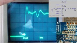
I've also attached some photos I took last night of how the attenuators are looking. The waveform on the right is from the diode attenuator (for LE), on the left is the resistive attenuator (for BCK, DL, DR). Probes set to x10.
My full system setup for reference:
QA550 ---> FIFO ---> I2S to PCM ---> Distinction v2 ---> CEN ---> Pass F5 Clone ---> Tang Band W8-1772 8" Neodymium Full Range Driver in Bob Brines TT200.
Today I will go over all the circuitry and make sure its behaving itself, then in the coming days upload the schematics and bom.
Cheers.
Hi Guys,
Attached are some photos of Distinction-1541 V2.
It sang straight to my heart last night, you can really feel the emotion in the music, very pleased to have it im my system. I feel content to move on and finalise this design.
I've also attached some photos I took last night of how the attenuators are looking. The waveform on the right is from the diode attenuator (for LE), on the left is the resistive attenuator (for BCK, DL, DR). Probes set to x10.
My full system setup for reference:
QA550 ---> FIFO ---> I2S to PCM ---> Distinction v2 ---> CEN ---> Pass F5 Clone ---> Tang Band W8-1772 8" Neodymium Full Range Driver in Bob Brines TT200.
Today I will go over all the circuitry and make sure its behaving itself, then in the coming days upload the schematics and bom.
Cheers.
Attachments

Awesome. I can imagine this is about as good as it gets. Thanks for sharing the complete audio chain. The SD into Ian's stuff as a source must be a great source.
What are you using now for the 26v source?
What are you using now for the 26v source?
Awesome. I can imagine this is about as good as it gets. Thanks for sharing the complete audio chain. The SD into Ian's stuff as a source must be a great source.
What are you using now for the 26v source?
No problem 🙂
The SD player is great in terms of sound quality, but a bit awkward to use due to the nature of SD cards. Not a bad compromise but I will try the WaveIO when I get a chance (your old one 😛).
26V source is coming from the Lab power supply at the moment, im really surprised it can sound as good as it does with a switch mode psu. Definitely upgrade soon though. It would be interesting to try a Capacitance multiplier, or a zener + emitter follower before the zener string. It may be sufficient enough to go with a very basic schottky rectifier ---> CLCRCR.
Cheers
How long will GB stay open after the design is finalized.
Hi buzzforb,
Ill buy enough PCBs to cover everyone on the interest list. So the GB will run until they are all gone.
Cheers
Playing on the "D2" tonight:
Just for fun, heres a clip of Paul Kelly - Love Letter playing on the new pcb.
Just for fun, heres a clip of Paul Kelly - Love Letter playing on the new pcb.
- Home
- Source & Line
- Digital Line Level
- TDA1541A Diy Pcb - "Distinction-1541 v2"