Anyway I don't understand how this should affect sound, because the data is shifted into the registers and the switches again see 5V swing 
Bernhard said:Anyway I don't understand how this should affect sound, ....
The interference into the substrate is lowest.
Bernhard said:.......... because the data is shifted into the registers and the switches again see 5V swing
As stated before: Logic in the TDA1541(A) is current routing logic, the logic swing is some hundreds of millivolts. This is one of the reasons that output voltage compliance is low, specified at 25mV.
regards,
HtP said:The interference into the substrate is lowest.
As stated before: Logic in the TDA1541(A) is current routing logic, the logic swing is some hundreds of millivolts. This is one of the reasons that output voltage compliance is low, specified at 25mV.
Okay, I start to understand.
The output voltage compliance reminds me to one idea I had regarding passive I/V conversion:
Take a resistor value that gives 2V for 2mA and connect to a buffer opamp.
Use the output of the opamp as floating ground for the ( analog and digital ) ground of the 1541.
The TDA doesn't see the output voltage anymore.
Will this work ?
What was ment here is where the current 'reference' generator circuit is, that it is supplied between the -5V and the -15V pins. With other words, the supply voltage of the current reference is 10V. This current reference is the reference for all binary weigthed currents in the TDA1541(A). The supply rejection ratio for this current reference is not infinite, thus this 10V should be as constant as possible
Using a single pre-regulator feeding both local -15V and -5V regulators would be beneficial?
One output (the not used) flows in pin 28, thus +5V. The outher output in pin 6, 25. The sum of signal currents in pin 6, 25 and pin 28 is constant. That means that it is advantageous to bring the output currents in pin 6, 25 back into the +5V supply. That can be done by e.g copying the output current into the +5V supply. If done correct, the signal in the +5V decoupling capacitor completely disapears.
maybe a problem with English language: what does it mean "copying the output current into the +5V supply" and how this can be done?
Thanks.
Paul
indeed it would be much better to understand if someone would post a power supply schematic following those advice given.
please tell me whats wrong
Not a mistake, but R2, R6, R9, R3, R4, R7 have not the values suggested by Henk ten Pierick.
Decoupling between VDD and VDD1 is missing (maybe between VDD1 and VDD2 too).
What values are needed to obtain a 1.2-1.6 V swing, as suggested by Htp?
And how to "copy" the currents out of pin 6, 25 to the VDD pin 28 ?
Paul

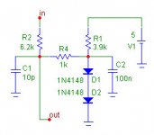


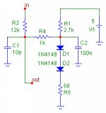
Bernhard why don't you use resistors values that give a 1.2-1.6V output?
yours give 1.1-1.9 when I simulate it
yours give 1.1-1.9 when I simulate it
Bricolo said:Bernhard why don't you use resistors values that give a 1.2-1.6V output?
yours give 1.1-1.9 when I simulate it
Because my simulator gives 1-1.8V
It is not possible to swing 200mV around 1.4V with 2 diodes.
2 diodes give 1.2V @ 1mA in my simulator
What about:
The way VDD1 is made from VDD2
I suppose that, due to different loads (VDD1 and VDD2), the way you showed with only one 7915 for both -5V and -15V, does not give good regulation.
My suggestion was to use a single pre-regulated -20V rail feeding two separate local shunt regulators, as seen in Thorsten's Adagio, TNT Convertus ecc. Since HtP stated that the current reference generator is supplied between the -5V and the -15V pins, I guess that a single supply rail gives a better ripple performance. Opinions?
Paul
Bernhard said:This one swings 1.2 - 1.6
This one gives me 1.35-1.75
I mean peak to peak, and without the caps (pure square output)
- Status
- Not open for further replies.
- Home
- Source & Line
- Digital Line Level
- TDA1541 info