GuidoB wrote a while ago:
I got all the parts to try dem-reclock, got a Philips 74HC161, because two shops had no 74/4024.
Wanted to figure it out myself how to use 161, but after all the datasheets i am still guessing. So before i'm ending up in a few evenings of trial and error:
How to connect the 74HC161 instead of the 74HC4024?
Thanks in advance!
So for me 74HC4024 or HC161
I got all the parts to try dem-reclock, got a Philips 74HC161, because two shops had no 74/4024.
Wanted to figure it out myself how to use 161, but after all the datasheets i am still guessing. So before i'm ending up in a few evenings of trial and error:
How to connect the 74HC161 instead of the 74HC4024?
Thanks in advance!
Hi,
I am implementing the provided DEM/BCK/DATA reclock scheme with 74VHC163s and 74VHC74s, parts I have at home, plus a 1ppm clock. The reclocking target is for the OS TDA1541A in my Marantz CD50SE.
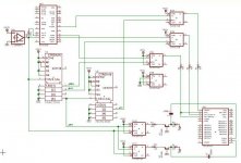
Would the attached schematic work theoretically?
Cheers,
honinbou
I am implementing the provided DEM/BCK/DATA reclock scheme with 74VHC163s and 74VHC74s, parts I have at home, plus a 1ppm clock. The reclocking target is for the OS TDA1541A in my Marantz CD50SE.
Would the attached schematic work theoretically?
Cheers,
honinbou
Attachments
1ppm?????
1ppm what? Frequency over temp? Absolute frequency? Jitter perhaps?????😕
honinbou said:Hi,
I am implementing the provided DEM/BCK/DATA reclock scheme with 74VHC163s and 74VHC74s, parts I have at home, plus a 1ppm clock. The reclocking target is for the OS TDA1541A in my Marantz CD50SE.
Would the attached schematic work theoretically?
Cheers,
honinbou
1ppm what? Frequency over temp? Absolute frequency? Jitter perhaps?????😕
Useless
you mean Temperature Quotient? Useless, completely useless!!!!!!🙄
honinbou said:I mean 1ppm TCXO
Cheers,
honinbou
you mean Temperature Quotient? Useless, completely useless!!!!!!🙄
Guess no one wants to tell me whether the connections on the schematic are fine?
Well, I guess I will get a perf board and test out the schematic myself.
honinbou
Well, I guess I will get a perf board and test out the schematic myself.
honinbou
Thanks Andypairo,
I just finished hardwiring the stuff with the 8fs for DEM. Hopefully I will have time to test the board with my CD50SE tonight.
Cheers,
honinbou
I just finished hardwiring the stuff with the 8fs for DEM. Hopefully I will have time to test the board with my CD50SE tonight.
Cheers,
honinbou
Hi tubee,
It does work, but I think I need a separate power transformer for the clock and the 74's. I am power everything with the original transformer inside the CD50, and I am worried about killing it! There is definitely a noticable improvement in the soundstage, but I don't know by how much.
May be I am fooling myself?
Good luck modifying!
Cheers,
honinbou
Thanks Honinbou
Did you made any alterations on your schematics?
Improvements can be fooling, i know that by now.
Example is Non-os: can be very nice, but sometimes it isn't, (then i must be tired of working or something...)
Can't do the original PS the (small) extra current? I want to supply the added logic pcb's also from original transformer.
Hi tubee,
Schematic remains the same, but DEMs are clocked at 8Fs. I used 74HC163s and 74VHC74s. -6V, 5V (except the TCXO) were taken directly from the mainboard.
honinbou
Schematic remains the same, but DEMs are clocked at 8Fs. I used 74HC163s and 74VHC74s. -6V, 5V (except the TCXO) were taken directly from the mainboard.
honinbou
There is definitely a noticable improvement in the soundstage, but I don't know by how much.
A/B'ed or not? Just saw two recent examples of people changing the wrong components in some components without schematic and they were sure they noticed a difference. (In some totally unrelated areas, like an RC4558 used for power, not sound, or the pair of caps for an other output stage)
Dragonmaster,
I don't have a spare capacitor to restore the CD player back to its pre-DEM mod state, so my result was not based on a real time A/B test.
Tubee,
I forgot to mention that I also removed the WS, BCK, and DATA reclock portion of the circuit. I couldn't get that part of the circuit to work. However, I guarantee 100% that DEM reclocking with 74VHC74N and 74HC163N works!
Cheers,
honinbou
Ok thanks Honinbou for info.
The /163 isell known, use a 74HC163 in free running mode, as clock divider after a separate clock (Tent &/or kwak)
Now i am busy with a pcb with 4 dacs parallel, TDA1541. Each dac gets a time shifted data input. The Dem is now realised standard with a (Philips KP) cap of 560 Pf.
I am curious to the sound and allmost cannot wait until it is ready and will give some music
But i wonder if it could be possible to build only one DEM reclock circuit, and reclock the 4 DEM inputs of 4 dacs together.
Hi,
After reading papers listed here http://www.diyaudio.com/forums/showthread.php?s=&threadid=31780&perpage=10&pagenumber=17
it seems DEM oscillator fs is independent from sample fs, runs at about 250Khz, and is the emiter coupled variety.
I assume in the td1541a the oscillator is capacitor based.
Does anyone have experience of designing ECL oscillators ?
edit: I'm not sure if I exactly understand the paper but my reading is that 'jitter' on the DEM will lead to unmatched current sources.
Resurrecting the thread...
....to ask some clarifications
In the various DEM schematics posted I noticed, apart from the use of different dividers, that pins 16 and 17 aren't treated in the same way:
-In Henk's original schematic the emitters of the BJTs get two out of phase signals
-In the schematic with synchronous counters (honinbou) the BJTs get two in phase signals
-In the DEM syncing proposed by ecdesigns pin 16 is coupled via a cap directly to the output of the flip/flop and pin 17 is left unconnected
Which schematic should I use?
Cheers
Andrea
Re: Resurrecting the thread...
Is it in that immense 110 page ultimate tda1541a thread?
Can you post a link ?
Andypairo said:....to ask some clarifications
-In the DEM syncing proposed by ecdesigns pin 16 is coupled via a cap directly to the output of the flip/flop and pin 17 is left unconnected
Which schematic should I use?
Cheers
Andrea
Is it in that immense 110 page ultimate tda1541a thread?
Can you post a link ?
- Home
- Source & Line
- Digital Line Level
- TDA1541 DEM reclocking