BTW
I tested befor few years, and TDA1540 and DAC chip can work at 384KHz SR. (Maybe more but that was max SR form amanero interface).
.
From the datasheets max rate is 12Mb/sec (against TDA1541A that have 6Mb/s). So TDA1540 have double speed.
I tested befor few years, and TDA1540 and DAC chip can work at 384KHz SR. (Maybe more but that was max SR form amanero interface).
.
From the datasheets max rate is 12Mb/sec (against TDA1541A that have 6Mb/s). So TDA1540 have double speed.
Hi Zoran
Yes I saw that you tested it at 384 kHz which is great.
But:
1) I think the limitation lies in the 14 bit resolution.
And no, the TDA1541 can not replace it unfortunately, at least not for the specific sound character of TDA1540.
2) Regarding higher sampling frequency I am also afraid that there is no sound improvement in that.
I did some A-B testing (with Sennheiser HD600 headphones) of oversampling versus non-oversampling in a Marantz CD45 where I mounted toggle switches to switch between Clock, Latch, Data L and Data R signals form either before or after the SAA7030 digital filter, and switching the 14bit/16bit leg on SAA7000 at the same time. Yes you can do that real time, for true A-B comparison.
The analogue filter was tuned to filter from 21 kHz instead of the original 36 kHz, because I could hear the digital noise was stressing the opamps into really 'screachy' highs. Yes, I have read that others (Lukas Lampizator Fikusz) just lets the analogue filter be, and claims they cannot hear the extra noise ....but I can! Clearly! And so could my client/customer on that project as well!
So there is no getting around it: Non-oversampling requires heavier filtering, and thereby also more phase shift at audible frequencies.
And still the Non-oversampling sounded better ... more 'live', more natural, more attack and even more perceived space between the musicians.
I think the positive difference for going non-oversampling is due to the lower clock frequency which the TDA1540 was operated at.
It could only be that or some other 'bad things' that happens in the SAA7030 digital filter.
What do you think?
Anyway if the TDA1540 sounds better at lower frequency sampling (with the same analogue filter) then I am afraid that a capability of playing 384kHz doesn't do much good.
Let me hear other opinons.
NB: We also need to test if Miro's converter circuit can operate at 96 - 192 - 384 kHz, and here I suspect that correct timing is even more critical than what I can trim with my slow 20 MHz scope, but of course it should be tried out at some time.
Last edited:
@Nrik
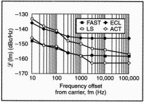
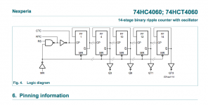
for higher frequencies try to use a 74AHCTxxx type of logic circuits, they are faster as the 74HCT type.
for higher frequencies try to use a 74AHCTxxx type of logic circuits, they are faster as the 74HCT type.
@Nrik
for higher frequencies try to use a 74AHCTxxx type of logic circuits, they are faster as the 74HCT type.
Hmm, they look nice.
Only 3,4nS propagation delay.
Only SMD though, and maybe only needed if we want to go 384 kHz sampling rate. I will se if I can test my through-hole prototype at 96 and 192 kHz.
However it will take me some time to get to that.
Hi Zoran
Yes I saw that you tested it at 384 kHz which is great.
But:
1) I think the limitation lies in the 14 bit resolution.
And no, the TDA1541 can not replace it unfortunately, at least not for the specific sound character of TDA1540.
2) Regarding higher sampling frequency I am also afraid that there is no sound improvement in that.
I did some A-B testing (with Sennheiser HD600 headphones) of oversampling versus non-oversampling in a Marantz CD45 where I mounted toggle switches to switch between Clock, Latch, Data L and Data R signals form either before or after the SAA7030 digital filter, and switching the 14bit/16bit leg on SAA7000 at the same time. Yes you can do that real time, for true A-B comparison.
The analogue filter was tuned to filter from 21 kHz instead of the original 36 kHz, because I could hear the digital noise was stressing the opamps into really 'screachy' highs. Yes, I have read that others (Lukas Lampizator Fikusz) just lets the analogue filter be, and claims they cannot hear the extra noise ....but I can! Clearly! And so could my client/customer on that project as well!
So there is no getting around it: Non-oversampling requires heavier filtering, and thereby also more phase shift at audible frequencies.
And still the Non-oversampling sounded better ... more 'live', more natural, more attack and even more perceived space between the musicians.
I think the positive difference for going non-oversampling is due to the lower clock frequency which the TDA1540 was operated at.
It could only be that or some other 'bad things' that happens in the SAA7030 digital filter.
What do you think?
Anyway if the TDA1540 sounds better at lower frequency sampling (with the same analogue filter) then I am afraid that a capability of playing 384kHz doesn't do much good.
Let me hear other opinons.
NB: We also need to test if Miro's converter circuit can operate at 96 - 192 - 384 kHz, and here I suspect that correct timing is even more critical than what I can trim with my slow 20 MHz scope, but of course it should be tried out at some time.
Yes indeed playing hig rates like 384KHz in NOS mode require music published originaly in that format. Which is very rare? I am listening NOS mode. So the material is mostly 44.1KHz up to 192KHz without changing SR on the computer player. Or CD transport via SPDIF link.
.
I can agree with You about the sound. Very good, natural (supernatural 🙂 ), transparent and keeping the diiferences in vocals and instruments. Reverberations effects are from "root" starting from low mid region, NOT just in the HF region like almost every contemporary (ultralow distortion dac) does. And siblants are great too - coming in package with very good ride cymbals 🙂. It just sounds good even without analog HF filter at the output.
.
TDA1541A is wery good (i tried in Time Sim mode 16bit format NOS, same analog output, diferent Riv value) but I prefer somehow TDA1540 bit more.
New function added:
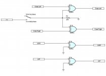
"Time Compensated Absolute Phase Inverter"
Inverting the absolute phase requires only inversion of the data signals, but to avoid screwing up the now perfectly synchronized signals, it is not optimal just to add an inverter in the signal path.
But luckily X-OR gates can function as both an inverter or a buffer, depending whether if the other input is set to VCC or to GND, and thereby adding the exact same delay to all the signals, no matter if they are inverted or buffered.
So therefore a 74HC86 quad X-OR is used.
The Latch and the Clock signal is just buffered, and for both the data left and data right signals a switch to VCC and a pull down resistor to GND sets the absolute phase for the audio signal.
It is tested, and it works.
Attachments
Hi Nrik 🙂
Thanks for posting upgrade. Yes I think that is the good way for invert phase. IF that is needed.
(I did data inversion few times to acheive correct phase out at some old school Iout dacs.)
.
The fact is that after I-V conversion with simple Riv at the output of ANY Iout dac, voltage is in opposite phase (180deg). But as the ususaly that level of voltage is low, and need to be amlified to some line level. The next amplification stage is usually single (tube or JFET stage) that also shift the phase for 180deg. So in the case of pasive Riv and sat tube SE anode follower stage, the phase is like it should be. 🙂
.
This information could be of use for TDA1540 because of low value of Riv.
Datas about 1540 is for 10mV offset (against 25mV offset for TDA1541A). For the same amount of Io current of 4mA p-p.
.
I done some SCK stopped mode. Will post sch later. 🙂
.
TDA1541A is wery good (i tried in Time Sim mode 16bit format NOS, same analog output, diferent Riv value) but I prefer somehow TDA1540 bit more.
I dunno if that helps, but I found you can really makes the TDA1541A (whatever it's a normal A, a non-A, a S1, a late Taiwan, all with different sounding signature at ISO pcb layout, parts and design, sounds different when you know where to work with in relation to what you hear. From casual to very damped, different high diferent bass... Give me a TDA1541A pcb and I can easily play with it in relation to the envy... and the system it playbacks.
It's a very sensitive chips about the grounding, the pcb layout, the decoupling, the front end, the power supplies toplogies...
Not sure you can perform an opinion between the both (but of course at Iso perimeter).
I find your works very interresting guys, it gives the envy to work more on this old chip 🙂
It was "No-PCB" Point-to-Point, all grounds under the chip, very stiff and close. Very good sounding but i think that I like just a nip more TDA1540? I wil try again 🙂
I spot that data in Miros schematic are right justified? So I made 14bit window for bit clock for "place" where the data will be.
.
EC design not shifting the data into right side. He is leaving the datas oriented like they was in left side. Left justified, LE relative.
.
EC design not shifting the data into right side. He is leaving the datas oriented like they was in left side. Left justified, LE relative.
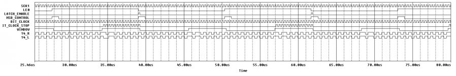
TDA1540 with stoped clock and right justified Time Simoultaneous
Circuit with stopped clock. (Module below working schematic.).
Datas are moved from left to the right justification regard to LE.
LE have just one-half of the bit clock.
Circuit with stopped clock. (Module below working schematic.).
Datas are moved from left to the right justification regard to LE.
LE have just one-half of the bit clock.
Attachments
Last edited:
I rearange ECdesign sch (16bit version) to 14 bit for TDA1540.
It was tricky becaus I didnh have Spice model for 4060 ic. But I made it from ither logic gates.
To see what happening and to adopt from 16bits to 14bits
Hes aproach is not to "touch" LE signal. AND to keep the datas Left oriented as in I2S bus.
will post the circuit latter...
It was tricky becaus I didnh have Spice model for 4060 ic. But I made it from ither logic gates.
To see what happening and to adopt from 16bits to 14bits
Hes aproach is not to "touch" LE signal. AND to keep the datas Left oriented as in I2S bus.
will post the circuit latter...
################## Model Data Report ##################
============= SPICE Model =================
.MODEL 4060B_5 d_chip ( behaviour= "
+;4060 14-STAGE BINARY COUNTER+OSC @5V
+/inputs MR RS IRTC ICTC
+/outputs ORTC OCTC O3 O4 O5 O6 O7 O8 O9 O11 O12 O13
+/wires CP
+;
+/module NAND_4060
+/inputs A N
+/outputs NAND
+/TABLE 2
+;A B NAND
+ L H L
+ X X H
+/endmodule
+/instance NAND_4060 MR RS ORTC
+/instance NAND_4060 MR ICTC CP
+;
+/module NOT_4060
+/inputs IN
+/outputs OUT
+/TABLE 2
+;IN OUT
+ L H
+ H L
+/endmodule
+/instance NOT_4060 IRTC OCTC
+;
+/module CNTR_4060
+/inputs MR CLK
+/outputs O3 O4 O5 O6 O7 O8 O9 O11 O12 O13
+/clock CLK - 10 1 2
+;SYNC
+;MR CLK F F F F F F F F F F F F O3 O4 O5 O6 O7 O8 O9 O11 O12 O13
+ X X X X X X X X X X X X F+0 F+1 F+2 F+3 F+4 F+5 F+6 F+7 F+8 F+9
+;ASYNC
+;MR CLK F F F F F F F F F F F F O3 O4 O5 O6 O7 O8 O9 O11 O12 O13
+ L X X X X X X X X X X X F0 F1 F2 F3 F4 F5 F6 F7 F8 F9
+ H X X X X X X X X X X X L L L L L L L L L L
+/TABLE 1
+;MR CLK F F F F F F F F F F O3 O4 O5 O6 O7 O8 O9 O11 O12 O13
+ X X X X X X X X X X X X F0 F1 F2 F3 F4 F5 F6 F7 F8 F9
+/endmodule
+/instance CNTR_4060 MR CP O3 O4 O5 O6 O7 O8 O9 O11 O12 O13
+/delay 20
+;input output Rise time Fall time
+ RS O3 420n 420n
+ RS O4 470n 470n
+ RS O5 520n 520n
+ RS O6 570n 570n
+ RS O7 620n 620n
+ RS O8 670n 670n
+ RS O9 720n 720n
+ RS O11 820n 820n
+ RS O12 870n 870n
+ RS O13 920n 920n
+ MR O3 X 200n
+ MR O4 X 200n
+ MR O5 X 200n
+ MR O6 X 200n
+ MR O7 X 200n
+ MR O8 X 200n
+ MR O9 X 200n
+ MR O11 X 200n
+ MR O12 X 200n
+ MR O13 X 200n
+/constraint 3
+; Name Event From Event To Min/Max Time
+ 'PULSE WIDTH' LH RS HL RS MIN 120n
+ 'PULSE WIDTH' LH MR HL MR MIN 50n
+ 'RECOVERY' HL MR LH RS MIN 160n
+")
============= Model template =================
a%p [%tMR?%t:d%t;MR
+ %tRS?%t:d%t;RS
+ %tRTC?%t:r%t;RTC
+ %tCTC?%t:r%t;CTC]
+ [%tRTC?%t:d%t;RTC
+ %tCTC?%t:d%t;CTC
+ %tO3?%t:d%t;O3
+ %tO4?%t:d%t;O4
+ %tO5?%t:d%t;O5
+ %tO6?%t:d%t;O6
+ %tO7?%t:d%t;O7
+ %tO8?%t:d%t;O8
+ %tO9?%t:d%t;O9
+ %tO11?%t:d%t;O11
+ %tO12?%t:d%t;O12
Hi 🙂
Thanks !
I emulate just for few FF and input stage from PHI logic for 4060.
I think that is maybe better to buid with separate logic parts? Because 4060 is not used like "full" ic?
.
Anyway 4060 has to be removed for 14bit operation, and repalced with another circuit.
I will post latter...
Thanks !
I emulate just for few FF and input stage from PHI logic for 4060.
I think that is maybe better to buid with separate logic parts? Because 4060 is not used like "full" ic?
.
Anyway 4060 has to be removed for 14bit operation, and repalced with another circuit.
I will post latter...
Attachments
Last edited:
I must say I quite like my Marantz TDA1540, and it has very few mods 🙂 (for instance still the ceramics caps for the DEMs I very don't like on a TDA1541A, uh ! I can imagine with some optimisation how more good it could be, yeah)
The TDA1540 has a “signature” but it is not “better or worse” then other Philips current source DAC’s. So it is up to your implementation of the chip and circuit if you can outperform any other dac.
Last edited:
I agree on that having played with the TDA1541A for 30 years 😀
I'm less in love with the 1543, I like more the TDA1545A instead but my daily dac is a S1 and sometimes late Taiwan TDA1541As
And some 32pins dac chip from Philips that came later were pretty good too !
I'm less in love with the 1543, I like more the TDA1545A instead but my daily dac is a S1 and sometimes late Taiwan TDA1541As
And some 32pins dac chip from Philips that came later were pretty good too !
I spot that data in Miros schematic are right justified? ...
Input data are standard I2S (64-Bit word).
Output data are right justified.
Anyway, nice work with the stop-clock 😉
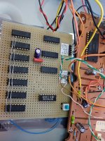
I can now confirm that Miro's circuit, including my addition of timing synchronisation plays anything up to 24bit/96khz beautiful without digital noise.
I tested it with I2S signals tapped from a SA9277 usb dac, and with an improvised 3,3V-5V level shifter circuit.
I tested it with I2S signals tapped from a SA9277 usb dac, and with an improvised 3,3V-5V level shifter circuit.
Attachments

- Home
- Source & Line
- Digital Line Level
- TDA1540 - I2S to Offset Binary, no CPLD, no FPGA