BC817-40 isn't a generic name in this instance, its the precise part I am using and fortunately its got a model in LTSpice. But you're right its not particularly critical - a lower gain (the -40 indicates the highest gain grouping) may indeed perform slightly better.
Not all transistors will perform as well here - I look for a couple of parameters. First is 'hoe' the output impedance, indicated in Spice models by the parameter 'VAF' - we want a high number as ideally a CS has infinite output impedance. Second we don't want the transistor to have a much lower 'hoe' close to its saturation region - this can be seen on the traditional transistor curve tracer plots. I'll post up some pics later to demonstrate what's important. I don't know about Digikey's pricing but the BC817 (its a SOT23, there are leaded equivalents) is one of the cheapest going - I got a reel of them (3k) and the price was under $30 so less than a cent each.
I meant "generic" in the sense that it appears to me that there are a few manufacturers making BC817-40 transistors. At least the high-level specs that DigiKey displays are all the same.
For example: DigiKey part number BC817-40LT1GOSCT-ND, ON Semiconductor BC817-40LT1G.
I just about ordered but then looked at the datasheet, and their biggest dimension is only 3mm. Given how simple this circuit is, I think I'll do it point-to-point with through-hole (leaded) components, and solder directly to the opamp socket pins on the bottom of the board (hoping I don't get "pin dyslexia" like I did with the tda1387 ICs).
So, how about DigiKey part number BC33740TACT-ND, Fairchild Semiconductor BC33740TA?
Ah I see your meaning now, yes the part is 'generic' in that sense, my apologies. All manufacturer's versions look to be the same.
Yes both of those BC337-40s will do the job fine. Pin dyslexia affects me too, I'm not too sure its easily defeatable, seems to be my inability to reflect the orientation of a part in my mind when looking from the other side of the PCB. Frustrating!
Yes both of those BC337-40s will do the job fine. Pin dyslexia affects me too, I'm not too sure its easily defeatable, seems to be my inability to reflect the orientation of a part in my mind when looking from the other side of the PCB. Frustrating!
I believe I have a handle on the constant-current source/opamp class-a biasing mod. I still have to order the parts, but aside from any goof-ups, should be a quick job.
So, following this mod, you hinted that...
You've remarked on this several times. If I understand correctly, one goal is to correct what you call the "NOS droop", which I believe is the high frequency rolloff associated with the steep artifact filter used in NOS DACs. Perhaps there are other goals as well?
Once again, if you can help out with some more details on this, I'd certainly appreciate it!
So, following this mod, you hinted that...
Beyond that the next big step is output LC filtering.
You've remarked on this several times. If I understand correctly, one goal is to correct what you call the "NOS droop", which I believe is the high frequency rolloff associated with the steep artifact filter used in NOS DACs. Perhaps there are other goals as well?
Once again, if you can help out with some more details on this, I'd certainly appreciate it!
This one's probably the most complex mod and there's more than one LC filter involved, depending on how far you wish to 'gild the lily'.
The simpler of the two mods is indeed what you referred to - correcting for the 'NOS droop' - something inherent in all DACs operating at 44.1kHz output sample rate. The way I do this is include an under-damped 2nd order filter which 'rings up' to lift the high frequency response. After the lift (in other words, at higher frequencies than audio) it provides some filtering too. Very few commercial NOS DACs have any sort of 'droop' correction - AMR's do but I'm not certain about any others.
The circuit details for this filter I've shown in post 24. Its inserted after the opamp stage, right at the output. The inductor (10mH) for this circuit is available at Mouser - MSS1210-106KEB Coilcraft | Mouser . Coilcraft are often happy to send out samples so it might be worth a try asking them direct.
This filter being only a 2nd order only provides a fairly gentle roll-off for the out of band images created by a NOS DAC. I've generally found that a somewhat steeper filter sounds better and I'll talk about that in the next post - as far as I'm aware no commercial NOS DAC uses a filter anything close to the ones I've been using.
The circuit details for this filter I've shown in post 24. Its inserted after the opamp stage, right at the output. The inductor (10mH) for this circuit is available at Mouser - MSS1210-106KEB Coilcraft | Mouser . Coilcraft are often happy to send out samples so it might be worth a try asking them direct.
I think the only follow-up question I have this time is if there are any special requirements for the caps and resistors (voltage, precision, dielectric, composition, tolerance, etc)? Post 24 and also your follow-up pics in post 25 are quite clear, even to me. 🙂 As with the op-amp constant current source mod, since it's a simple circuit with just a few components, I'll probably use leaded components and point-to-point wiring.
Edit: one more question, how many of those Coilcraft inductors will be required once all the mods are done? Just trying to economize on shipping costs...
Thanks again!
Last edited:
For the caps, I've used NP0 ceramics but they're SMT, you could use pretty much any film caps (steer away from mylar though) as you'll probably want leaded. I'll go to Mouser and see what the best bang for the buck is and get back. Resistors - standard metal film leaded will be superior to the thick film that I've used.
Excellent question about the Coilcrafts - if you go the whole hog on the mods the balanced anti-imaging filter takes 8 of the 10mH. I split the output filter into two inductors in mine but I doubt that's essential so stick with just 10mH. You'll need 10 10mH in total. But then if you do go balanced you'll need an output transformer, the cores of which again come from Mouser. So do you need a full list?
Excellent question about the Coilcrafts - if you go the whole hog on the mods the balanced anti-imaging filter takes 8 of the 10mH. I split the output filter into two inductors in mine but I doubt that's essential so stick with just 10mH. You'll need 10 10mH in total. But then if you do go balanced you'll need an output transformer, the cores of which again come from Mouser. So do you need a full list?
Capacitor suggestions for the output filter :
220nF Wima - MKS2C032201B00KSSD WIMA | Mouser
3.9nF Kemet - PHE426DJ4390JR05 Kemet | Mouser
Given the tolerances are 5% I think 3.9nF is close enough to the 4nF I used in LTSpice.
220nF Wima - MKS2C032201B00KSSD WIMA | Mouser
3.9nF Kemet - PHE426DJ4390JR05 Kemet | Mouser
Given the tolerances are 5% I think 3.9nF is close enough to the 4nF I used in LTSpice.
Excellent question about the Coilcrafts - if you go the whole hog on the mods the balanced anti-imaging filter takes 8 of the 10mH. I split the output filter into two inductors in mine but I doubt that's essential so stick with just 10mH. You'll need 10 10mH in total. But then if you do go balanced you'll need an output transformer, the cores of which again come from Mouser. So do you need a full list?
I think I'm good for now. Waiting on parts, then the CCS mod and NOS droop filter should keep me busy for a bit. Plus, Coilcraft is sending me a few of those inductors as free samples. (Though Mouser lists them, they actually don't sell them, you have to buy direct from CC.)
Side note, I ordered another one of these DACs from seller "doukmall" on ebay. They are sending me a 110v version stock, and also sold a couple extra 110v trannies. I'll report when I receive them, but maybe the stock 110v availability makes this little gem more appealing to the USA audience.
Capacitor suggestions for the output filter :
220nF Wima - MKS2C032201B00KSSD WIMA | Mouser
3.9nF Kemet - PHE426DJ4390JR05 Kemet | Mouser
Given the tolerances are 5% I think 3.9nF is close enough to the 4nF I used in LTSpice.
Thank you for that! I had already picked out some parts, not these exact ones, but close enough to confirm that I'm on the right track. And, you anticipated my next question, is 3.9nF (or 4.1nF) acceptable, since Mouser doesn't appear to sell 4nF leaded film caps.
Once again, much thanks for all your help and encouragement!
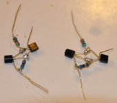
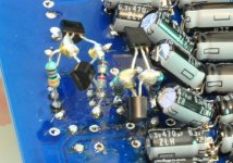
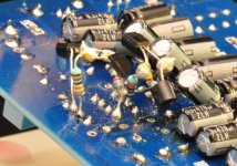
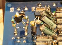
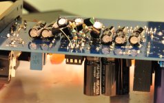
Op-amp constant current source mod completed! As Han Solo said, "She may not look like much, but she's got it where it counts." I definitely gave up any chance of ever putting this back in the case. But, I decided that this one I've been hacking on will be the "beta" version. When I've completed all the mods I think I'll go through and redo them all more neatly on another unit. (Or if I'm feeling courageous, maybe try to design a purpose-built PCB...)
I thought point-to-point would be easy... it's not hard so much as it is tedious. Just getting everything to stay in place before I actually started soldering required a lot of lead-bending with tiny needle-nose pliers.
Anyway, here are some pics.
I thought point-to-point would be easy... it's not hard so much as it is tedious. Just getting everything to stay in place before I actually started soldering required a lot of lead-bending with tiny needle-nose pliers.
Anyway, here are some pics.
Attachments
Love all those 'air sculptures' - maybe I'll post up some more of mine soon 🙂
So how's the temperature of the AD845s now? I remembered after posting this mod that you'd not decreased their supply yet so they must be getting quite toasty with the extra 8mA or so of bias? Oh and any change to how it sounds?
So how's the temperature of the AD845s now? I remembered after posting this mod that you'd not decreased their supply yet so they must be getting quite toasty with the extra 8mA or so of bias? Oh and any change to how it sounds?
Love all those 'air sculptures' - maybe I'll post up some more of mine soon 🙂
That would be neat, I'm interested in seeing what your fully-modded board(s) look like.
So how's the temperature of the AD845s now? I remembered after posting this mod that you'd not decreased their supply yet so they must be getting quite toasty with the extra 8mA or so of bias? Oh and any change to how it sounds?
That is correct, I have not decreased the supply voltage. Though based on what you said, seems like there is no reason not to. Maybe I'll try to do that before the weekend is over...
I let the DAC run all night, after I finished around midnight. So it's been running for almost 10 hours straight. I used to have one of those infrared laser temperature guns, but now I can't find it. I'll have to use the "finger on the IC" method of taking the AD845's temperature. 🙂
As for the sound change... it's not dramatic, but I think things are just a bit smoother, maybe a bit more bass tightness/definition. But maybe that's just expectation bias? It's definitely not hurting anything, that's for sure (well, unless I'm cooking the opamps).
Yep - I've got a cheap Marantz CD player here, with great baubles hanging down from the underside - have to put the whole thing on substantial edge blocks, to keep the vulnerables from being main supports for the beast, 😀 !Love all those 'air sculptures' - maybe I'll post up some more of mine soon 🙂
There's an aspect of this design which I've not sat down and fully clarified in my mind and that's the output offset voltage. I mention it now because it impacts the amount you can reduce the supply voltage on your opamps.
The TDA1387s have an internal fixed current source to the positive supply (DS says 1.08mA) and the digitally controlled current source (could be called 'DAC proper', 0 - 1mA sink) sits between the output and the negative supply (0V). This means with digital zero applied to the chip, there's a positive output current around 580uA. Multiply that by 8 for the number of paralleled DACs and its 4.6mA.
That 4.6mA has to be supplied by the opamp, meaning its output must go negative a sufficient amount to balance it out. I seem to recall that the stock I/V resistor is in the region of 600-700 ohms so this'll give an output offset up to -3.2V. The maximum negative swing of the opamp is when the 'DAC proper' is sinking 0mA so the full 1.08mA*8 comes from the opamp. This is a swing to -6V.
What I did on mine was install another current source to cancel the offset at the output of the opamp, this to allow me a lower supply voltage than would be possible with the offset. My offset's bigger because I'm running my TDA1387s at 6V and their internal current sources scale with supply voltage - so I can't run my output opamps at +/-8V supply without reducing the offset.
It looks as if you can just about reduce your supplies to 8V without worrying about cancelling the offset.
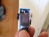
tda1387x4
hi,
this is my implementation of 4xtda1387 on my aune m1 dap. it by passibg the headphone stage and volume, using 1.3k iv resistor directly to headphone jack out to drive my 16ohm iem.
the other is when i attached to amanero using coupling capt om pin7 avx edlc low esr for 0.022mf
any suggestion on implement the tda on my dap?
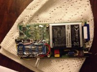
Attachments
So are you saying you have 4 TDA1387s (=4mA) and your I/V resistor is 1.3kohms? This gives too wide a voltage swing so you'll get clipping. But if you put the resistor in parallel with your 16ohm headphones you'll be in effect current driving the 'phones. But with only 4mA peak-to-peak current your peak power is just 64uW - its going to sound jolly quiet, perhaps 30dB down from maximum level?
hi richard,
so what is the best value so i can still use the ext amp after the dap?
i put resistor 1.3k from current out pin 6/8 to ground does it mean parrarel to mu headphone?
best regards
so what is the best value so i can still use the ext amp after the dap?
i put resistor 1.3k from current out pin 6/8 to ground does it mean parrarel to mu headphone?
best regards
If you're using an external amp to drive the phones and just want the Aune to work as a DAC then your maximum swing of 0 - 3.5V needs to be divided by the current (4mA) to get the I/V resistor - in this case 820ohms (nearest standard value).
If you put the headphones in parallel with the resistor the DAC will 'see' the headphone resistance and the I/V resistor is largely irrelevant (coz the headphones are much lower resistance).
If you put the headphones in parallel with the resistor the DAC will 'see' the headphone resistance and the I/V resistor is largely irrelevant (coz the headphones are much lower resistance).
- Home
- Source & Line
- Digital Line Level
- TDA1387 x8 DAC: let's check its design, mod it -or not-, play music -or not! :(-