Seeking help on CCS mod
Abraxalito,
Greetings!
I'm having trouble locate BC33740 (suggested part on Matt's Wiki) at my place.
I am using AD845 Opamps on my DAC.
You used the BC817 - however IIRC you are not using any opamps in the DAC.
Choices I have found are (with Mouser links for checking out the specs):
KSC1815YTA
KSC1815YTA Fairchild Semiconductor | Mouser
2N3906
2N3906 ON Semiconductor | Mouser
SS8050
SS8050BBU Fairchild Semiconductor | Mouser
C2328A
KSC2328AYTA Fairchild Semiconductor | Mouser
BC548
BC548B ON Semiconductor | Mouser
Will any of these work? 🙂
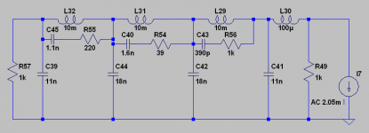
Not quite. The aim of the LC filter is only in part to remove the unnatural brightness - in fact that can be got rid of by other means. I found an AD830 didn't generate the brightness when used as a post-amplifier, no inductors required there. So the brightness is I take it the way that certain ICs react to being fed with glitches, not all ICs are so sensitive.
The main reason to put in an LC filter is to get rid of the out-of-band images which tend to create extra distortion (IMD) in preamps and amps. When I first started out I used passive I/V so did have an arrangement of passive I/V -> LC -> amp. But turns out the DAC works better with active I/V so now I have active I/V -> active filter.
Thanks for the kind words - I would mention though that from my point of view its not 'hard work' rather just being interested and following my passion, for fun 🙂
can you share your schematic of your active filter and active I/V here, I want compare and what is improvement from that your new topology, since now I used your passive I/V and LC filter.
Attachments
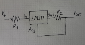
Yes please if you wouldn't mind 🙂 I replaced the 3 bridges with 12x 1a schottkys to improve the supply so if the 317 mod takes the psrr further I'll add that also.
Here you go - the resistor values you need depend on the current. For example the stock 8 DAC analog supply needs almost 50mA for the DAC chips themselves, add on a few mA for the shunt so the R2 value then needs to be 22ohms. R1 should be chosen so as not to leave too large a voltage drop across the LM317 - I've found they have a tendency to oscillate when dropping higher voltages. Ideally leave no more than 5V across it - any excess drop across R1.
Attachments
I'm having trouble locate BC33740 (suggested part on Matt's Wiki) at my place.
Most of those will work fine yes - except the 2N3906 which is a PNP. You'd need 2N3904 which is the equivalent NPN. If you have a choice, go for the lowest current rated one which hopefully will also have the lowest parasitic capacitance.
This one looks especially good - I wonder if there's an SMT version I'd like to try it out if there is 🙂
can you share your schematic of your active filter and active I/V here, I want compare and what is improvement from that your new topology, since now I used your passive I/V and LC filter.
The active I/V I've shown on my blog already, its here - http://www.diyaudio.com/forums/blogs/abraxalito/1283-discrete-transistor-based-cfb-i-v-stage.html
As for the active filter it would be a fair amount of work to draw that up in schematic form as I have it in shorthand only in my notebook at the moment. If you were to share something of your build and listening impressions with the LC filter then I'd be inclined to reciprocate.
Sorry if it's a bit offtopic 😱
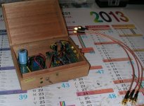
Some news from my side, i've almost finished to build the 4xTDA1387 (only one hole to drill for the power socket left) 🙂
I've tested different values of capacitors and resistors and i found that 1k i/v resistors coupled with 1nf ceramics and 100uf electrolytics at the output sound best (dac supplied with 5.8V and it does not seem to heat up even a bit) 😎
The wait to receive decent capacitors (elna silmic II) and the dc power socket is killing me because it sounds already absolutely fantastic unpolished 😀
Attachments
Sorry if it's a bit offtopic 😱
Some news from my side, i've almost finished to build the 4xTDA1387 (only one hole to drill for the power socket left) 🙂
I've tested different values of capacitors and resistors and i found that 1k i/v resistors coupled with 1nf ceramics and 100uf electrolytics at the output sound best (dac supplied with 5.8V and it does not seem to heat up even a bit) 😎
The wait to receive decent capacitors (elna silmic II) and the dc power socket is killing me because it sounds already absolutely fantastic unpolished 😀
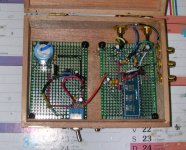
Any chance you could post a "bird's eye" view of the build, looking down directly on the circuit (i.e. just the stuff inside the case)?
Are you using that "1541 Transfer" tda1387x4 board from ebay that you linked earlier (I think it's marketed as a drop-in replacement for the famous tda1541, but uses 4x tda1387, which are much cheaper).
I think you might get some benefit from some of the mods for the x8 discussed here. In particular, that "transfer" board uses the same 104/105 SMD ceramics for pin7 and pin5 de-coupling. At least on the x8 DAC (main topic of this thread), I noticed an immediate and definitive bass boost when I removed the little pin7 ceramics and replaced them with 1000uF electrolytics.
Also... taking an idea from Abraxalito's "next gen" mods. You could basically build two of what you have now, but instead of directly paralleling the I2S signal between boards, put an inverter in there. So board one will be doing R+ and L+, and board two will do R- and L-, giving you balanced output.
Yes it is 😉Are you using that "1541 Transfer" tda1387x4 board from ebay that you linked earlier (I think it's marketed as a drop-in replacement for the famous tda1541, but uses 4x tda1387, which are much cheaper).
It's full of empty space and pretty not optimized but it's the very first electronic project that i have made so far.
Yeah i did read many of thoses mods posted here but i already soldered the chip for the second time (after desoldering it from a previous proto board since i waited too long for my breadboard to arrive because i wanted to test it). 😱I think you might get some benefit from some of the mods for the x8 discussed here. In particular, that "transfer" board uses the same 104/105 SMD ceramics for pin7 and pin5 de-coupling. At least on the x8 DAC (main topic of this thread), I noticed an immediate and definitive bass boost when I removed the little pin7 ceramics and replaced them with 1000uF electrolytics.
As you know too much heating can irremediably deteriorate thoses tda1387 so i prefer to finish this project as it is as a raw successful first attempt and start a new more advanced dac later (considering its price it won't hurt to buy a bunch of thoses anyway). 🙂
Replacing the 22uf by 100uf and pushing voltage supply near 6V already have a big impact in bass and relief, making it overall a strong competitor against a stock muse 4xTDA1543 (because it's cheaper, purer and it is even a foot-tapping device where you can focus on details if you feel like it).
I'm completely conquered but it won't discourage me to make a 4xtda1543 dac as well using the same topoly for comparing results and why not maybe a 10xtda1543 (using pavouk design) just for the sake of it. 😎
That sounds great indeed as much as discrete i/v stage or advanced filters but it's really not at my actual electronics level of knowledge 😛Also... taking an idea from Abraxalito's "next gen" mods. You could basically build two of what you have now, but instead of directly paralleling the I2S signal between boards, put an inverter in there. So board one will be doing R+ and L+, and board two will do R- and L-, giving you balanced output.
Attachments
It's full of empty space and pretty not optimized but it's the very first electronic project that i have made so far.
Thanks for the pic! I don't think you're giving yourself enough credit. It looks quite clean for a first project! And I've seen plenty of experienced people post pics of far messier work. 🙂
Yeah i did read many of thoses mods posted here but i already soldered the chip for the second time (after desoldering it from a previous proto board since i waited too long for my breadboard to arrive because i wanted to test it). 😱
Are you talking about soldering the individual tda1387 chips, or the big "meta" chip? If you haven't done any soldering directly on the tda1387 chips, you can just solder the caps directly to them. Leave the SMD ceramics so you don't have to un-solder the meta board. Just an idea!
I'm completely conquered but it won't discourage me to make a 4xtda1543 dac as well using the same topoly for comparing results and why not maybe a 10xtda1543 (using pavouk design) just for the sake of it. 😎
See, now you've got the "bug" and are already thinking about your next projects. 🙂
That sounds great indeed as much as discrete i/v stage or advanced filters but it's really not at my actual electronics level of knowledge 😛
I have quite minimal knowledge as well... I pick up little bits here and there from copying others, and from folks like Abraxalito who are very generous with their time to explain stuff that is over my head. It's not a fast or necessarily efficient way to learn, but it's fun. And now I'm thinking about projects that are still "basic" by most standards, but well beyond what I would have tackled a couple years ago. So that's progress!
Anyway, thanks for sharing. Eventually, I'll circle back and revisit the tda1387 chips in their various forms.
Thanks i wanted to make it as clean and simple as possible to keep it easy to fix if something is going wrong. 🙂Thanks for the pic! I don't think you're giving yourself enough credit. It looks quite clean for a first project! And I've seen plenty of experienced people post pics of far messier work.
Even by touching the DIP28 pins with the tip of the soldering iron (regulated at +-40W) for desoldering it can get burning hot in the tda1387 legs area so i just assumed it was pretty risky to do this multiple time. 😉Are you talking about soldering the individual tda1387 chips, or the big "meta" chip? If you haven't done any soldering directly on the tda1387 chips, you can just solder the caps directly to them. Leave the SMD ceramics so you don't have to un-solder the meta board. Just an idea!
That a nice idea for sure but with my actual soldering skill i would be scared to bridge some pins with solder or heating it too much and kill the traces. 😱
I waited a long time before acquiring some decent audio stuff considering that 3 years ago i was still using a cheap 2.1 sound kit and an intergrated motherboard chipset.See, now you've got the "bug" and are already thinking about your next projects.
So now it's time for me to enjoy good sounding audio devices and that's why i got it this fast and already think about what is coming next.😛
My pleasure, finding rendering differences between various dac is really fun especially when you discover hidden parts in your favorite songs (btw i don't find the tda1387 fatiguing anymore even with an AKG k701). 😉Anyway, thanks for sharing. Eventually, I'll circle back and revisit the tda1387 chips in their various forms.
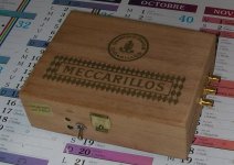
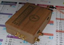
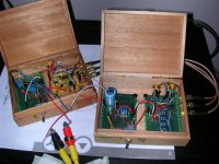
Made the i2s box today and prepared hole and space to add toslink interface later 🙂
Attachments
Thanks for the pic! I don't think you're giving yourself enough credit. It looks quite clean for a first project! And I've seen plenty of experienced people post pics of far messier work. 🙂
+1 looks amazing to me - cleaner than anything I've built and I'm not exactly on my first project....😛
I have quite minimal knowledge as well... I pick up little bits here and there from copying others, and from folks like Abraxalito who are very generous with their time to explain stuff that is over my head. It's not a fast or necessarily efficient way to learn, but it's fun.
I'd say (my day job is a teacher but I'm not normally teaching EE) its a jolly effective way to learn. I can't think of a more effective one but I am open to suggestions.
Anyway, thanks for sharing. Eventually, I'll circle back and revisit the tda1387 chips in their various forms.
Yeah, thanks for sharing!
+1 looks amazing to me - cleaner than anything I've built and I'm not exactly on my first project....😛
I'd say (my day job is a teacher but I'm not normally teaching EE) its a jolly effective way to learn. I can't think of a more effective one but I am open to suggestions.
Yeah, thanks for sharing!

Many thanks to you again for making this thing works, it has really given me the desire to pursue those experimentations 🙂
I'd say (my day job is a teacher but I'm not normally teaching EE) its a jolly effective way to learn. I can't think of a more effective one but I am open to suggestions.
Yeah, thanks for sharing!
Agree with Abraxalito, im accountant and learning alot about creating audio gear in this forum, especially about dac to abraxalito..
by the way, what is maks v supply for tda 1387?
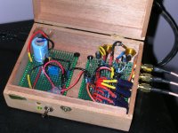
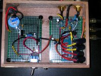
I'm still waiting for the last components to arrive and had some spare time.
Received and mounted the dc input sockets and changed the crappiest wires around the dac by thick bare cooper salvaged from a dead psu.
I experienced a lot of things to optimize a bit the cabling to avoid hum and ground loop and learned from my errors what i should avoid doing in my next dac projects. 🙂
The sound was then increadibly pure and transparent with a noise free output that pushed me to supply it with 6V to add a bit of gain.
While it sounded splendid on bassy recordings it was still a bit too clean for the brighter ones. 🙄
So i soldered 1500uF caps (that was the closest to 1000uF i had at hand) between Vref and ground while keeping ceramics under the board (that should preserve those electrolytics life spam anyway ?) to add a bit of bass for lacking recordings. 😉
I may solder a switch later to change between this new warmer and deeper render and its previous clear analityc output (this is like a two in one DAC now 😀).
I don't know yet if elna silmic II caps at output will push it to an another level but damn it's impressive as it is and after that i'm done with tda1387 for now. 😉
Not definitive pics here because it needs to be optimized a bit with wires and coponents placement but it fit.
Attachments
Folks:
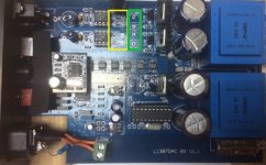
I'm grateful for the guidance that abraxalito, Matt, Malefoda and others have provided on modifying this DAC and have been enjoying making the improvements detailed in the wiki, but have run into a problem with the "Increase Decoupling of Analog Stage" modification in that I cannot seem to clear the solder from some of the vias for the four film caps. I've never had this problem before; solder suckers, a RatShak suction device, solder wick, nothing has worked. I'm concerned I may have damaged the board in that area (marked by the yellow box). As an alternative, could I simply create a "bus bar" using the vias for the electrolytic caps (marked by the green box) and hang multiple caps off that, akin to what abraxalito suggested for the "Increase TDA1387 Chip Supply Capacitance" mod?
Thanks for helping this old codger out!
Regards,
Scott
Attachments
Scott,
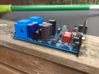
I didn't use the vias for the film caps - just installed upgraded electrolytics in place of the original ones, per photo attached.
I would have thought you'd be able to install the new cap by applying the soldering iron to the lead while pushing it into the via to clear the it.
Cheers,
Jon
I didn't use the vias for the film caps - just installed upgraded electrolytics in place of the original ones, per photo attached.
I would have thought you'd be able to install the new cap by applying the soldering iron to the lead while pushing it into the via to clear the it.
Cheers,
Jon
Attachments
I cannot seem to clear the solder from some of the vias for the four film caps. I've never had this problem before; solder suckers, a RatShak suction device, solder wick, nothing has worked.
I used to struggle with clearing old solder out of holes as well until I acquired a pin vise. It's basically a device the size of a pen or pencil that can hold tiny drill bits at the tip. You can use this to drill through solder that is reluctant to come out.
I think these are available from numerous sources. I bought mine from McMaster-Carr. Pin vise part number 8455A31. I bought the following three drill bits: 2912A247, 2912A252, 2912A242. (Although in practice I only ever use the biggest one.)
Scott,
I didn't use the vias for the film caps - just installed upgraded electrolytics in place of the original ones, per photo attached.
I would have thought you'd be able to install the new cap by applying the soldering iron to the lead while pushing it into the via to clear the it.
Cheers,
Jon
Jon:
I tried that as well. This is really embarrassing to admit, but I have spent a ridiculous amount of time trying to remove the solder from those vias. Solder suckers don't work purely through suction -- they rely on the surface tension of the solder, so it is usually better to add a little more solder than to try to remove a tiny amount. In this case, nothing I've tried has worked. In any event, this has never happened to me before.
I used to struggle with clearing old solder out of holes as well until I acquired a pin vise. It's basically a device the size of a pen or pencil that can hold tiny drill bits at the tip. You can use this to drill through solder that is reluctant to come out.
I think these are available from numerous sources. I bought mine from McMaster-Carr. Pin vise part number 8455A31. I bought the following three drill bits: 2912A247, 2912A252, 2912A242. (Although in practice I only ever use the biggest one.)
Matt:
That's it, I'm sold. And you just became my hero.
Thanks guys,
Scott
- Home
- Source & Line
- Digital Line Level
- TDA1387 x8 DAC: let's check its design, mod it -or not-, play music -or not! :(-