From Tob Toon pitcures i made a quick schema of what i think it is made of :

Am i right, wrong ?
The schematic doesn't look to me as if it'll work - it has AC coupling from the DAC outputs.
What should i add or change to get the 4xTDA1387 output works as intended (i think that the result should be something not that far from 2 Vrms).
What's the intention? 2VRMS will never be attainable from a passive stage after a TDA1387 (with the exception of using a step-up trafo).
Robert:
Thank you!
Regards,
Scott
The schematic doesn't look to me as if it'll work - it has AC coupling from the DAC outputs.
What's the intention? 2VRMS will never be attainable from a passive stage after a TDA1387 (with the exception of using a step-up trafo).
Thanks for your repply.
My bad, I should have misunderstood Vpp with Vrms when the manufacturer said it has 2V output, so it should be around 0.7Vrms 😱
The intention is just to have a decent output level that don't require me to push the stereo amplifier volume more than 1/4 of its course for a proximity listening (something the stock Muse TDA1543x4 does whitout problem for exemple) using just some resistors and capacitors.
Are resistors used as a voltage divider to get 2V from the 3V output of the DAC and then the DC is blocked by the caps just before the RCA connector while some are just here for filtering ?
Should the two outputs share the same return to ground from their resistor divider end or should they be completely separated ? Should I care about Vref and Ibias or just leave it as it is with just a capacitor to GND ?
Is a certain amount of current really needed If the dac has a VDC output ?
The way to get the dac outputs into something usable for the amplifier is a bit obscure and tricky to me (i'm trying my best to learn the way i/v or v/i converters work but i don't really know how to apply it to audio application and DAC specs yet).
Sorry again if it sounds silly 🙁
I can't recall what the power supply voltage was on the Muse in stock form, my vague memory was it was over 6V so potentially swings more voltage on its output than a TDA1387 which has an absolute max supply rating of 6V. With 6V the TDA1387 can probably swing about 4 or maybe 4.5V peak-peak. For which it would need an output resistor of 3.9k or 4.3k to 0V.
Seeing as TDA1387 isn't a voltage output DAC, it can't generate voltage without resistance to 0V. The simplest solution would be to put the above 3k9 (or 4k3) resistors in, with a smallish parallel capacitor (say 1nF max) also to 0V. Then run your 22uF caps between the output pins and your output sockets, +ve side to the TDA1387. Add two 100k resistors between the -ve terminal of the 22uFs and 0V.
Seeing as TDA1387 isn't a voltage output DAC, it can't generate voltage without resistance to 0V. The simplest solution would be to put the above 3k9 (or 4k3) resistors in, with a smallish parallel capacitor (say 1nF max) also to 0V. Then run your 22uF caps between the output pins and your output sockets, +ve side to the TDA1387. Add two 100k resistors between the -ve terminal of the 22uFs and 0V.
I can't recall what the power supply voltage was on the Muse in stock form, my vague memory was it was over 6V so potentially swings more voltage on its output than a TDA1387 which has an absolute max supply rating of 6V. With 6V the TDA1387 can probably swing about 4 or maybe 4.5V peak-peak. For which it would need an output resistor of 3.9k or 4.3k to 0V.
Seeing as TDA1387 isn't a voltage output DAC, it can't generate voltage without resistance to 0V. The simplest solution would be to put the above 3k9 (or 4k3) resistors in, with a smallish parallel capacitor (say 1nF max) also to 0V. Then run your 22uF caps between the output pins and your output sockets, +ve side to the TDA1387. Add two 100k resistors between the -ve terminal of the 22uFs and 0V.
Many thanks for the hints abraxalito 😉
That should looks like that ?
I've tried to experiment with simple res voltage dividers (composed with 1K and 220R and it start to gives some listenable experience but spoiled by some click and pops 😀
I will try as soon as possible your circuit and return here to give the results 😎
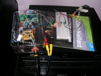
Attachments
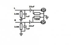
That should looks like that ?
Yeah, congratulations - a perfect copy of what was in my mind's eye 🙂
I will try as soon as possible your circuit and return here to give the results 😎
Looking forward to hearing of your listening feedback.
After some trial and error it worked like it should thanks to you abraxalito. 😉
I firstly tried with 4.7K resistor (that's all i have at hand and don't wanted to use 3 or 4 for approaching the true value anyway 🙄) but it sounded distorded, replacing them by 1 K solved the issue.
It may also be due to some touching components, bad placement or contacts. 😀
Even with my poorly done soldering job, noisy psu's and low quality components i have at hand i must say that i'm purely impressed by the result. 😎

That's a really pleasing sound, way brighter than philips cd player based around tda5141 and tda1543, i heard some hidden details than i hadn't before. 🙂
I will play with some values and try to understand clearly how it works.
Any ideas of how to suppress those little pops sounding like Vinyl that can appear (will bying quality componenets should resolve the issue) ?
Could bypassing 22uF caps with ceramic can do some good to smooth the output of those little parasitic noise by chance ?
In any case Big thanks to you
I firstly tried with 4.7K resistor (that's all i have at hand and don't wanted to use 3 or 4 for approaching the true value anyway 🙄) but it sounded distorded, replacing them by 1 K solved the issue.
It may also be due to some touching components, bad placement or contacts. 😀
Even with my poorly done soldering job, noisy psu's and low quality components i have at hand i must say that i'm purely impressed by the result. 😎
That's a really pleasing sound, way brighter than philips cd player based around tda5141 and tda1543, i heard some hidden details than i hadn't before. 🙂
I will play with some values and try to understand clearly how it works.
Any ideas of how to suppress those little pops sounding like Vinyl that can appear (will bying quality componenets should resolve the issue) ?
Could bypassing 22uF caps with ceramic can do some good to smooth the output of those little parasitic noise by chance ?
In any case Big thanks to you
Attachments
..................
I found this 4X TDA1387 Parallel Transfer Board Audiophile HiFi DIY Sound Close to TDA1541 | eBay searching for TDA1387 and thought "what a cool little thing we have here"
I have purchased some of these "adapters".
I tried them in a REVOX B226S with excellent results.
Andy
Ok i was so in a hurry that i completely forgot about wiring i2s board ground to the one of the tda1387 
All is clear now and the only noise i can hear is coming from the usb and the dac psu (i have to push the amplifier volume level to more than 3/4 without music and stand at less than a meter away from the speaker to hear anything).😱
Considering my poorly done assembly i find the result really incredible, i find it livier than the 4xtda1543dac.
I will finish this dac as soon as a receive the components i bought and will solder sockets for easy swap of different values/types of capacitors and replace resistors by tripot. 🙂
I think that a better power source regulated with some lm317 from a wall transformer power supply should give even better results. 😉
Is it even possible to swap a TDA1541a by this chip without modding the i/v stage I tried it first in my Marantz CD-883 and it was dead silent with it 😕
Anyway it has already some spectacular results bare used considering its price 🙂
It's really tempting to give a shot with two or four of them 😀 but i'm not sure if the gain in the specs would really be perceptible (active or discrete i/v may be needed) 🙄
All is clear now and the only noise i can hear is coming from the usb and the dac psu (i have to push the amplifier volume level to more than 3/4 without music and stand at less than a meter away from the speaker to hear anything).😱
Considering my poorly done assembly i find the result really incredible, i find it livier than the 4xtda1543dac.
I will finish this dac as soon as a receive the components i bought and will solder sockets for easy swap of different values/types of capacitors and replace resistors by tripot. 🙂
I think that a better power source regulated with some lm317 from a wall transformer power supply should give even better results. 😉
I have purchased some of these "adapters".
I tried them in a REVOX B226S with excellent results.
Andy
Is it even possible to swap a TDA1541a by this chip without modding the i/v stage
I tried it first in my Marantz CD-883 and it was dead silent with it 😕Anyway it has already some spectacular results bare used considering its price 🙂
It's really tempting to give a shot with two or four of them 😀 but i'm not sure if the gain in the specs would really be perceptible (active or discrete i/v may be needed) 🙄
TDA1387 sounds 'livelier' than TDA1543 yes - might be because its more accurate but also might be because its adding false detail to some downstream component. CMOS DACs create glitches on their power supplies so have this 'feature' which bipolar DACs lack.
In some of my earliest experiments with TDA1387 I was using AD605 after a low valued I/V resistor and found that I could control the amount of false detail being added through judicious use of ferrite beads between the DAC and the AD605.
In some of my earliest experiments with TDA1387 I was using AD605 after a low valued I/V resistor and found that I could control the amount of false detail being added through judicious use of ferrite beads between the DAC and the AD605.
TDA1387 sounds 'livelier' than TDA1543 yes - might be because its more accurate but also might be because its adding false detail to some downstream component. CMOS DACs create glitches on their power supplies so have this 'feature' which bipolar DACs lack.
In some of my earliest experiments with TDA1387 I was using AD605 after a low valued I/V resistor and found that I could control the amount of false detail being added through judicious use of ferrite beads between the DAC and the AD605.
Interesting piece of information for sure, could some inductors be useful to reduce those "glitches" in place of ferrite beads ?
Are you referring to those false details as "shiny" cymbals sounds for exemple ? Because it's also kind of present with tda1543 but not at this level.
That makes TDA1387 a bit more fatiguing to listen but it's also a richier sound which is pleasant for recordings lacking life.
Gain/power amplifier could be a fun way to explore the potential of this dac and can easily be made by adding sockets and jumpers but it also means that noise will be amplified too (and that scares me a bit).
Yes you most certainly can use inductors - probably they'll do a better job if the filter's designed right. The beads I used had inductance around 1uH, I needed at least a dozen of them.
The false detail might well occur on cymbals yes, also on sibilants in voices, almost anything with 'an edge' to the sound. Yes its fatiguing in the mid- to long term - I always am after a long term listening kind of style in my designs, rather than a sound that initially impresses but grates after a time.
The false detail might well occur on cymbals yes, also on sibilants in voices, almost anything with 'an edge' to the sound. Yes its fatiguing in the mid- to long term - I always am after a long term listening kind of style in my designs, rather than a sound that initially impresses but grates after a time.
Yes you most certainly can use inductors - probably they'll do a better job if the filter's designed right. The beads I used had inductance around 1uH, I needed at least a dozen of them.
So to soften the tda1387 brightness you use some kind of LC filter (where ferrite beads or inductors attenuates/soften the responsible frequency range) just after outputs and before i/v conversion ? 😕
I saw some of your blog entries and i must say that i'm really impressed by all your hard work, you sure know how to get the most of your audio equipments and those soldering skills are killing me. 😱
The false detail might well occur on cymbals yes, also on sibilants in voices, almost anything with 'an edge' to the sound. Yes its fatiguing in the mid- to long term - I always am after a long term listening kind of style in my designs, rather than a sound that initially impresses but grates after a time.
Yes that's why i'm fond of TDA1541 and TDA1543 philips cd players and based DAC, you can listen music for hours with it because you focus more on the dynamic of the songs than the details (it's almost as warm sounding as cassette without the flaws). 😉
I find the TDA1387 to be a nice addition and will soon try different components/values to get the best of it in its simpliest form considering my amateurish level. 🙂
So to soften the tda1387 brightness you use some kind of LC filter (where ferrite beads or inductors attenuates/soften the responsible frequency range) just after outputs and before i/v conversion ? 😕
Not quite. The aim of the LC filter is only in part to remove the unnatural brightness - in fact that can be got rid of by other means. I found an AD830 didn't generate the brightness when used as a post-amplifier, no inductors required there. So the brightness is I take it the way that certain ICs react to being fed with glitches, not all ICs are so sensitive.
The main reason to put in an LC filter is to get rid of the out-of-band images which tend to create extra distortion (IMD) in preamps and amps. When I first started out I used passive I/V so did have an arrangement of passive I/V -> LC -> amp. But turns out the DAC works better with active I/V so now I have active I/V -> active filter.
I saw some of your blog entries and i must say that i'm really impressed by all your hard work, you sure know how to get the most of your audio equipments and those soldering skills are killing me. 😱
Thanks for the kind words - I would mention though that from my point of view its not 'hard work' rather just being interested and following my passion, for fun 🙂
I was searching for filters exemples and found this Filters nice stuff that i will be able to understand now.
That's some very useful knowledge for someone like me. 🙂
So Active i/v and active filter are both op-amp based ?
Would a simple power supply using a virtual ground to get positive and negative voltages from a positive one would be enough for driving op-amp solutions ? 😕
One to set the gain with resistors to get a high level output (by adding positive or negative voltage to the singal based on what it receive and where it is connected) and one that will actively block or let pass a certain range of frequencies considered as noise and add another gain just after ?
As soon as i have enough time i will read and learn how those really works. Electronics sure can be fun when you can actually hear the results. 😉
Many thanks again for your active participation in this forum it's a pleasure to read your advices. 🙂
So Active i/v and active filter are both op-amp based ?
You're kidding right? No opamps - partly because they're really, really difficult to get sounding great and partly because (other than TL084s) they're more expensive than discrete transistors. Oh and added to that, for some of the stages I needed more bandwidth than a normal opamp would provide and high speed opamps need heroic efforts on power supply decoupling (and probably classA biassing as well). So I've pretty much abandoned opamps for high quality audio.
The active I/V schematic is on my blog - I followed a current-feedback topology (similar to AD844) but instead of going fully complementary I made it single-ended and biassed the stages against current sources. So its mostly classA, unlike IC CFB amps which are classAB.
Would a simple power supply using a virtual ground to get positive and negative voltages from a positive one would be enough for driving op-amp solutions ? 😕
As I've abandoned opamps I'm not able to answer this with any up to date experience. When I do use opamps I normally run them on a single supply rather than a balanced one, to circumvent some PSRR issues. Usually the -ve rail has the compensation capacitor so -ve rail PSRR sucks, hence I'll use this rail as the signal ground reference. The mid-rail potential (termed 0V in balanced supplies) I design so it sources/sinks very little current by running balanced and decouple it only to the -ve rail.
Many thanks again for your active participation in this forum it's a pleasure to read your advices. 🙂
Thanks for your interest 🙂
LM317T mod
Yes please if you wouldn't mind 🙂 I replaced the 3 bridges with 12x 1a schottkys to improve the supply so if the 317 mod takes the psrr further I'll add that also.
If you (or others) are interested I could hand draw a schematic to show how to put in an LM317T in place of the resistor. I did this mod and it has very decent bang-for-the-buck given an LM317T is a cheap part.
Yes please if you wouldn't mind 🙂 I replaced the 3 bridges with 12x 1a schottkys to improve the supply so if the 317 mod takes the psrr further I'll add that also.
You're kidding right? No opamps - partly because they're really, really difficult to get sounding great and partly because (other than TL084s) they're more expensive than discrete transistors. Oh and added to that, for some of the stages I needed more bandwidth than a normal opamp would provide and high speed opamps need heroic efforts on power supply decoupling (and probably classA biassing as well). So I've pretty much abandoned opamps for high quality audio.
Sorry if it has offended you, i'm completely a newbie with those things and just though it was working the same way. 😱
The active I/V schematic is on my blog - I followed a current-feedback topology (similar to AD844) but instead of going fully complementary I made it single-ended and biassed the stages against current sources. So its mostly classA, unlike IC CFB amps which are classAB.
As I've abandoned opamps I'm not able to answer this with any up to date experience. When I do use opamps I normally run them on a single supply rather than a balanced one, to circumvent some PSRR issues. Usually the -ve rail has the compensation capacitor so -ve rail PSRR sucks, hence I'll use this rail as the signal ground reference. The mid-rail potential (termed 0V in balanced supplies) I design so it sources/sinks very little current by running balanced and decouple it only to the -ve rail.
Thanks for your interest 🙂
I will read those tutorials to understand the basics and analyse your work on your blog next. 😉
It may take me a while to get a decent level but it sounds like something fun to learn and very useful for advanced project. 🙂
Sorry if it has offended you, i'm completely a newbie with those things and just though it was working the same way. 😱
Hey no offense taken here, just having a bit of fun 🙂 I used to design with opamps, only in the past year or so I've discovered that using discretes isn't so hard and often more cost-effective.
It may take me a while to get a decent level but it sounds like something fun to learn and very useful for advanced project. 🙂
The important aspect is always to enjoy yourself and have fun learning!
- Home
- Source & Line
- Digital Line Level
- TDA1387 x8 DAC: let's check its design, mod it -or not-, play music -or not! :(-