With -1V on pin7, looks like your opamps have lost +ve power. Pin7 should be +15V, assuming you've not adjusted the PSU voltage as suggested in my mods.
Thinking about your diagnosis, I took another look, I measure +15v on the +15v hole at the end of the capacitor, right before the opamp. Yet none on the op-amps. I bridged with a wire to avoid the lifted trace, but I get the same result. Green bars on the pic indicate the capacitors I have in at the moment.
I am out of ideas, this is the first time I am trying to fix a circuit. I might order another one, mod with more caution, and keep this one for spare parts. This thing sounded good.
I am out of ideas, this is the first time I am trying to fix a circuit. I might order another one, mod with more caution, and keep this one for spare parts. This thing sounded good.
Attachments
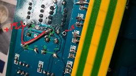
Aaand it's back online! I jump wired the 15v+ directly from the cap to the pin7s of the lm6171s. I think the traces between the caps and opamp sockets must be cracked. Thanks for your support abraxalito.
Just a heads up that the LJM Cm6331a card I got off ebay works perfectly with this DAC through coax. With my other sources ( bluetooth and Chromecast audio) on toslink I occasionally get fairly loud pops/white noise from connecting/disconnecting. This one remains quiet even when I take out the USB plug. The sound seems to have improved as well, a bit smoother and more bass drive.
CM6631A 24bit 192kHz USB to Coaxial Optical Fiber SPDIF I2S Converter DAC Board | eBay
Btw. going from 220uf to 470uf on the pin7s helped the bass a lot. I can't fit in more under the board, but, as others have reported, it's well worth putting in as much as possible.
Someone could make a real nice group buy PCB for the TDA1387.
Not meant for DIYing...
Also, what's the intellectual fun/challenge in reworking a device that's already pretty good to go (that unmodded 8xTDA1387 box)?
While DIYing from scratch -- PCB and all -- is going too far (especially for a subpar/jellybean DAC such as TDA1387/1545A), Veroboard and point-to-point is a happy medium.

...it's cheaper, avail. everywhere, and you can see and easily repair traces ...
At the price point of that good-to-go DAC, it's not really meant for durability (i.e, pathological DIYing). You may have cracked the trace during experimentation.I am out of ideas, this is the first time I am trying to fix a circuit.
Also, what's the intellectual fun/challenge in reworking a device that's already pretty good to go (that unmodded 8xTDA1387 box)?
While DIYing from scratch -- PCB and all -- is going too far (especially for a subpar/jellybean DAC such as TDA1387/1545A), Veroboard and point-to-point is a happy medium.
Next time ...I might order another one, mod with more caution, and keep this one for spare parts.
...it's cheaper, avail. everywhere, and you can see and easily repair traces ...
At the price point of that good-to-go DAC, it's not really meant for durability (i.e, pathological DIYing). You may have cracked the trace during experimentation.
Also, what's the intellectual fun/challenge in reworking a device that's already pretty good to go (that unmodded 8xTDA1387 box)?
.... Veroboard and point-to-point is a happy medium.
A point to point dac would be fun to try. Stock, this DAC lacked bass, and it had a weird rough top-end , so it's not exactly good-to-go. A few basic mods and it's in a completely different ball-park. Someone with more skill and better tools than I have would not have had any broken traces.
A very good question - I've given it quite a lot of thought, its a really tough one to find an ideal place for a volume control. Because I've not found so far an ideal solution I've not modded any of my DACs so far with volume controls. But eventually I'll just have to bite the bullet....
Here are some ideas if anyone wants to have a play.
Firstly the TDA1387 has a reference voltage - in essence its a multiplying DAC, the output current is a multiplication of the digital input by an internal reference current set by the voltage on pin7. This means if you have a way to adjust the pin7 voltage you have a volume control of sorts.
In practice its by no means a simple solution because the pin7 voltage is low under normal conditions (with a 5V supply, 0.83V). To lower the volume you need to arrange this voltage to go lower. But we already have a cap on this pin to get low enough noise - there's a danger that any mechanism we introduce to lower pin7's voltage will also introduce noise, degrading the SQ.
A 'digital' solution would work, by which I mean arrange an array of MOSFETs with sources to 0V and different value resistors in series with their drains, which then all connect to pin7. It probably needs software to control the switching of the multiple FETs but it won't introduce any noise. A caveat is the volume control will be a bit gradual because of the presence of the pin7 capacitor - it slows down any changes to the pin7 voltage. Anyone who's up for programming a microcontroller could use this method to implement at least a 20dB range volume control - I have tried playing with adjusting pin7's voltage and it works fine. It can be done on the otherwise unmodded DAC.
My other possibilities only apply to modded versions of the DAC.
Volume control ...
Nothin' fancy ... Just stick a GOOD Alps (etc.) analog pot before the output stage (whether this is discrete or opa).
There is another possibility: a two- or three-position gain (level) switch, as used in the Chu-Moy headphone amp:
https://web.archive.org/web/20150119011802/http://headwize.com/?page_id=707

... best to start off simple ... and you can go digital for remote control ... or if the DIY bug starts biting again.
Nothin' fancy ... Just stick a GOOD Alps (etc.) analog pot before the output stage (whether this is discrete or opa).
There is another possibility: a two- or three-position gain (level) switch, as used in the Chu-Moy headphone amp:
https://web.archive.org/web/20150119011802/http://headwize.com/?page_id=707
... best to start off simple ... and you can go digital for remote control ... or if the DIY bug starts biting again.
I'm interested int he other possibilities! Which mods are required?
There are a couple of possibilities. Firstly to place a multiplier element in the current output of the DAC - the mod that needs to have been done is the discrete I/V stage as the multiplier is an enhancement of that. I've not tried this so its a relatively high risk approach - essentially it involves a 'Gilbert cell' style multiplier.
The second way is very low risk but will take a lot of time - that's creating multiple secondary taps on the output transformer. Naturally enough this only applies to a DAC modded with the OPT. Its the ultimate 'take no prisoners' approach to doing a volume control - its the equivalent of having a TVC.
The ferrite cores I have been using tend to have limited numbers of terminals for windings so probably to get a good range of volume you'd need 2 or perhaps even 3 transformers per channel, all custom-wound. Hence a fair degree of dedication is required but the reward is unparalleled transparency.
The three methods I've outlined could of course be combined.
Thanks abraxalito. I don't have those mods applied, so I think I'll hold off on this for the time being.
I've been thinking about adding a remote with volume control to my Raspberry PI / Volumio / TDA1387 DAC based setup. I guess the most simple way of doing this would be to use a (motorised) pot as hollowman pointed out. Would the best place to put that be the input of the opamp, or just out the output to the RXA jacks?
Cheers,
Jon
If you have a more-or-less stock DAC there's nowhere obvious to fit a pot for volume. That's because the DAC chips are current-out and the output opamps are the first and last place where a voltage is generated. Putting a pot after the opamps would be problematic because when driving cables we need a lowish output impedance. The Zout of a pot is relatively high, and variable.
You could potentially use your pot to control the voltage at pin7 but I don't recommend putting DC onto a pot, it tends to degrade the wiper-track contact integrity.
You could potentially use your pot to control the voltage at pin7 but I don't recommend putting DC onto a pot, it tends to degrade the wiper-track contact integrity.
Last edited:
Putting a pot after the opamps would be problematic because when driving cables we need a lowish output impedance. The Zout of a pot is relatively high, and variable.
Maybe it's OK if the cables are fairly short? And how short is "fairly" short? 🙂
I kinda-sorta do this, but I put the pot near the amp, i.e. between the RCA jacks and the amp inputs. Then we're talking really short cables. (Although now I'm trying to put unbalanced to balanced transformers between the pot and amp, and meeting with mixed success, but that's another story.)
I've been thinking about adding a remote with volume control to my Raspberry PI / Volumio / TDA1387 DAC based setup. I guess the most simple way of doing this would be to use a (motorised) pot as hollowman pointed out. Would the best place to put that be the input of the opamp, or just out the output to the RXA jacks?
Jon, while putting a pot just before the RCAs in the DAC may be suboptimal, the upside is that it's easy. So you could give it a try and see if it works for your ears/setup. I've also seen people build super cheap/simple "passive preamps" by simply putting a pot in a little box with RCAs on either side.
Of course there's always the active preamp route.
Have you tried simply using the volume control on your Raspberry Pi with Volumio? Obviously at this point you're no longer sending the bit-perfect audio stream to the DAC, but maybe your ears won't notice? Or maybe you're neurotic like me and just knowing that you're messing with the bits is enough to be a problem. 🙂 That, and I also prefer having a physical knob for volume adjustment rather than messing with the mouse.
I don't know if Volumio supports this, but Foobar2000 will allow you to use more bits and apply dithering. So if you're mostly playing 16-bit CD audio, outputting 24 bits plus dithering should in theory give you enough extra "bit space" for volume control without having to corrupt the original bitstream too much. At least I think that's right. 🙂 But either way, the problem here is the tda1387 DAC only supports up to 16 bit audio.
In other news: I've had my eye on the Soekris dam1021 DAC for a while now. I finally caved and ordered one. The board alone cost 2x as much as the tda1387x8, we'll see if it offers any sonic improvement. (It does have built-in digital volume control though.)
Maybe it's OK if the cables are fairly short? And how short is "fairly" short? 🙂
Yeah its quite OK for short (i.e. low capacitance) cables. But it depends somewhat on the value. I'm of the persuasion that higher valued pots are better (easier to drive = better dynamics) so 47k is the minimum I'd suggest and ideally I'd go for 250k. For a 47k pot the maximum Zout is at halfway and about 12k. If your cable is short (say 1m or less) that should contribute under 200pF of capacitance, from a 12k source this gives a low pass filter with fc = 66kHz. So there will be a very slight droop at 20kHz but nothing to worry about.
The cable will need to be a well screened one as the source impedance is high.
Sounds like you might appreciate a TVC from this then? I'm looking into designing a TVC at the moment, using some PQ20/20 cores, its early days yet. Driving trafos - they don't want to see appreciable source resistance so putting them after a 47k pot I'd say is a no-no. But I've never tried this so have no idea how it sounds....I kinda-sorta do this, but I put the pot near the amp, i.e. between the RCA jacks and the amp inputs. Then we're talking really short cables. (Although now I'm trying to put unbalanced to balanced transformers between the pot and amp, and meeting with mixed success, but that's another story.)
I shall be very interested in your listening report if you do a side by side comparison of the two 🙂In other news: I've had my eye on the Soekris dam1021 DAC for a while now. I finally caved and ordered one. The board alone cost 2x as much as the tda1387x8, we'll see if it offers any sonic improvement. (It does have built-in digital volume control though.)
<edit> Since posting I've realized my advice in the first paragraph omits the loading effect of the amplifier input. Many amps have RC filters at their input which are designed on the assumption that the source impedance is low (i.e. under 1kohm). This should be investigated as the input filter when driven from 12k may have a bigger influence than the cable capacitance.
Last edited:
Have a look at diyparadise.com. Years ago, they evolved the TDA1545A "Monica' DAC to their "own" discrete DAC. Not sure either product (kit or parts) are still for sale.I've had my eye on the Soekris dam1021 DAC for a while now. I finally caved and ordered one. The board alone cost 2x as much as the tda1387x8, we'll see if it offers any sonic improvement. (It does have built-in digital volume control though.)
My main point being: parallel DACs, continuous-calibration DACs (1387/1545A) and discrete DACs are all previously-tread grounds. The problem is that (possibly due to little interest, DIY or manuf. level), no one seems to be "tracking" previous efforts. So needless "reinventions" are a result. Or self-interested parties/individuals want to take credit for "their" innovations.
Yeah... your 'scuse is that Google is banned in your land ... so you have to re-discover the wheel.
hi, i'm new around here and this is my first post 
It's really nice to see so much interesting informations about old philips dac's and I/V stage here (even if i don't clearly understand it all atm ).
).
I found this 4X TDA1387 Parallel Transfer Board Audiophile HiFi DIY Sound Close to TDA1541 | eBay searching for TDA1387 and thought "what a cool little thing we have here"
I wanted to give it a try and bought both this and a spdif to i2s adapter, wishing to make a small dac out of it (only fed with power and i2s). 🙄
I already own a 4xTDA1543 from Muse and its stock passive i/v stage is close as perfect for me and my needs. 🙂
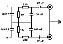
Tob Toon posted a 4xTDA1387 Dac here http://www.diyaudio.com/forums/digi...gn-mod-not-play-music-not-10.html#post4315988 which i suppose also use a passive i/v that should be close to the 4xTDA1543 in terms of output level. 😕
From Tob Toon pitcures i made a quick schema of what i think it is made of :

Am i right, wrong ? What should i add or change to get the 4xTDA1387 output works as intended (i think that the result should be something not that far from 2 Vrms).
Sorry if it sounds dumb, but my limited electronic knowledge is really an obstacle here. 😱
Thanks in advance for your answers.
Best regards.
It's really nice to see so much interesting informations about old philips dac's and I/V stage here (even if i don't clearly understand it all atm
).I found this 4X TDA1387 Parallel Transfer Board Audiophile HiFi DIY Sound Close to TDA1541 | eBay searching for TDA1387 and thought "what a cool little thing we have here"
I wanted to give it a try and bought both this and a spdif to i2s adapter, wishing to make a small dac out of it (only fed with power and i2s). 🙄
I already own a 4xTDA1543 from Muse and its stock passive i/v stage is close as perfect for me and my needs. 🙂
Tob Toon posted a 4xTDA1387 Dac here http://www.diyaudio.com/forums/digi...gn-mod-not-play-music-not-10.html#post4315988 which i suppose also use a passive i/v that should be close to the 4xTDA1543 in terms of output level. 😕
From Tob Toon pitcures i made a quick schema of what i think it is made of :
Am i right, wrong ? What should i add or change to get the 4xTDA1387 output works as intended (i think that the result should be something not that far from 2 Vrms).
Sorry if it sounds dumb, but my limited electronic knowledge is really an obstacle here. 😱
Thanks in advance for your answers.
Best regards.
Attachments
Matt, abraxalito & Co.:
Is the wiki that Matt organized still available anywhere? It took me longer than expected to get up and running on this project, but I'm game to start messing with this DAC's innards. Malefoda generously supplied a pair of LT1028s, which made a huge difference, and now I'm ready to dive down the rabbit hole.
Where oh where might that great guide be hiding?
Regards (and much appreciation),
Scott
- Home
- Source & Line
- Digital Line Level
- TDA1387 x8 DAC: let's check its design, mod it -or not-, play music -or not! :(-