Edit: looks like all or most diyAudio wikis are down now, see the Wiki down? thread over in the "Forum Problems" sub-forum. Site admin says hopefully in a week it will be back.
Ah, fair enough.
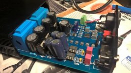
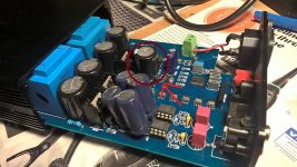
I got mine today. I put in some LM6171s and removed the 2n2 caps. It sounds promising so far. The only thing I am missing is the bass, so I'll have to add the capacitance on pin 7.
I also picked up some bass by replacing the existing supply caps some bigger uF low esr caps.
Try adding the KA 15k uF nichicon on pin 7
Try adding the KA 15k uF nichicon on pin 7
I also picked up some bass by replacing the existing supply caps some bigger uF low esr caps.
Ordering caps today, the plan so far :
1. 8x 6.3v 470uf Nichicon FG for pin 7 . Those can go either on top or on bottom, not sure what's easiest with my limited skills.
2. Big KA cap on main dac supply position.
3. 1 or 2 Low ESR for the Opamp decoupling, remove grey films.
4. Replace elko output dc caps with Wima MKS2 4.7uf.
I just had a look at your picture. Nice job fitting all of that in there! You added smaller (Oscon?) ones on the chip as well as that a big KA further away as the first main cap.
Do you recommend replacing the 4 caps right in front of the transformers? Yours are different than mine. I cannot read their value on mine, I suppose I should replace with good 35v/50v for safety.
The output caps, I already have good 1uf and 1.5uf lying around, would these cut off bass compared to 4.7uf?
Thanks.
I can think only of a downside from fitting higher voltage caps than necessary. That is that they're physically bigger so you can't get as high capacitance fitted into the space.
You could look into feeding the shunt regs from current sources (in place of the resistors there currently) then the amount of capacitance won't matter nearly as much.
You could look into feeding the shunt regs from current sources (in place of the resistors there currently) then the amount of capacitance won't matter nearly as much.
I can think only of a downside from fitting higher voltage caps than necessary. That is that they're physically bigger so you can't get as high capacitance fitted into the space.
You could look into feeding the shunt regs from current sources (in place of the resistors there currently) then the amount of capacitance won't matter nearly as much.
Thanks, I measured the chassis height, there is about 3.5cm of space on top. Not enough for higher voltage caps. The remark about shunt regs goes over my head, I'll need to learn what all these parts do. For now I'm just replacing caps according to recommendations in the thread.
About the Opamp decoupling, why do you recommend increasing the cap values? I read in other places that 100uf is sufficient and bigger not advisable due to impedance issues. Perhaps it is due to the way the Opamps are applied here?
I am impressed with this dac. Especially classical music is so clear and inviting, it just sounds right.
Poor advice...
Most Chinese USB converters do offer I2S. Use those three lines, preferably buffering them along the way.
Come on, braxy ... don't give these guys 'nother 'scuse to scoff.
This is poor advice. S/PDIF is a huge compromise.The normal way of implementing USB on Chinese DACs is for the USB receiver to convert to S/PDIF, this output is then routed into the CS8416.
Most Chinese USB converters do offer I2S. Use those three lines, preferably buffering them along the way.
Come on, braxy ... don't give these guys 'nother 'scuse to scoff.
The remark about shunt regs goes over my head, I'll need to learn what all these parts do.
If you (or others) are interested I could hand draw a schematic to show how to put in an LM317T in place of the resistor. I did this mod and it has very decent bang-for-the-buck given an LM317T is a cheap part.
About the Opamp decoupling, why do you recommend increasing the cap values? I read in other places that 100uf is sufficient and bigger not advisable due to impedance issues. Perhaps it is due to the way the Opamps are applied here?
I'd hazard that those 'other places' weren't places where people listened to the results of changing decoupling. I suggest as large as can be fitted in close to the opamp because here the device is called on to output up to 8mA which creates a fair amount of supply noise given the classAB output stage inside the opamp.
I am impressed with this dac. Especially classical music is so clear and inviting, it just sounds right.
My collection is almost totally classical and I concur. Still delighted with how mine sounds.
This is poor advice.
Clouseau: Does your dog bite?
Hotel Clerk: No.
Clouseau: [bowing down to pet the dog] Nice doggie.
[Dog barks and bites Clouseau in the hand]
Clouseau: I thought you said your dog did not bite!
Hotel Clerk: That is not my dog.
If you (or others) are interested I could hand draw a schematic to show how to put in an LM317T in place of the resistor. I did this mod and it has very decent bang-for-the-buck given an LM317T is a cheap part.
That would be much appreciated for future reference. I suppose it would be good to reduce the opamp supply voltage with the regulator in place, those parts do get warm.
I've been reading the lm317t datasheet and am first going to try a 5v circuit on a breadboard, looks like a useful thing to learn.
I removed the 105 ceramics but found out afterwards (stupid) that my replacement caps won't fit under the board. They are 6.3mm diameter, but the space is only 6mm in my case. I do not think I can manage to solder directly onto the pins, my soldering skills are rough. Would it be ok to try the dac without the 105 caps in place ? I did increase the size of the main pin 7 cap to a 8200uf 6.3v Panasonic FR. Otherwise I'll have to look for 5mm caps.
Attachments
Last edited:
My Pin 7 caps were also 6.3mm - I don't recall exactly what they were. They do fit if they're completely flush with the PCB. I found I had to install some below the PCB, and some above because the pins of the opamps prevented them being completely flush.
Edit: there are some photos in post #280
Edit: there are some photos in post #280
Last edited:
Would it be ok to try the dac without the 105 caps in place ?
Its not going to do any kind of damage to run the DAC without them, no. I predict a dearth of bass 🙂
I did increase the size of the main pin 7 cap to a 8200uf 6.3v Panasonic FR. Otherwise I'll have to look for 5mm caps.
A main pin7 cap? So you wired all the pin7s together? Yeah that's definitely an option if you can't fit individual smaller caps closer to the chips. I haven't found any 5mm caps suitable for this, mine also are 6.3mm.
My Pin 7 caps were also 6.3mm - I don't recall exactly what they were. They do fit if they're completely flush with the PCB.
Edit: there are some photos in post #280
Thanks, I did think 6.3mm would fit from reports in this thread. But it impossible to insert the cap between the pcb and chassis.
Its not going to do any kind of damage to run the DAC without them, no. I predict a dearth of bass 🙂
A main pin7 cap? So you wired all the pin7s together?
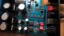
I did not wire them together. I thought the bigger supply cap near the corner of the row of tda1387s would have this purpose, since it was mentioned that putting in 15k uf 6.3v and more ( I see some have 3 big ones there) would increase bass too. I marked it in the picture. My bad 😱
I ordered some Chemi-con KZH 220uf 6.3v that are 5mm.
Panasonic have 150uf 6.3v FR/FM series with 5mm Diameter.
Attachments
Ah I see it was calling it a 'pin7 cap' which confused me - on the supplies it becomes a pin5 cap 🙂 Yes adding more did improve the bass for me.
ATTN: Philosophical sig-line fan-boyz
So chalk up another round of confusion, like your latest pessimistic philosophy hero.
(ATTN: DIYer's new to the forum: They are just unread books on the show-off drawing room book shelf. Pithy quotes are visionless.)
If you do hear a difference, it may very well be the converter. If the converter is well-designed (clean power, short paths, good grounds), the converter can act as re-clocker/buffer.A short status update on the TDA1545 DAC design - I now have a basic prototype working with the following structure -
- I2S to EIAJ conversion (3 74HC logic chips)
So chalk up another round of confusion, like your latest pessimistic philosophy hero.
(ATTN: DIYer's new to the forum: They are just unread books on the show-off drawing room book shelf. Pithy quotes are visionless.)
It will depend on the mod state. In stock form there are some series resistors on the opamp outputs to ensure stability into cable loads and provide a little low-pass filtering. They'll determine the output impedance as the opamps themselves have very low Zout, at least at audio frequencies (sub 1ohm typically). On my silkscreen they're marked as 75R, so I reckon that's the answer you're looking for.
Hmm, the dac will only give music from one channel. I checked all my soldering joints and retouched them on the side that does not work. I also ran it outside the chassis. I put my DMM on the RCAs, both show some voltage activity. Changed output caps just to be sure, same thing. Maybe I damaged a trace. Any thoughts?
Given you still have one working channel, the fault must be in the analog output stage of the failed channel. Any fault in the digital section would impact both channels.
Check the DC voltage on the opamp output pins (pin6).
Check the DC voltage on the opamp output pins (pin6).
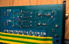
First I swapped left right op-amps. They work ok. I checked the panny caps before the opamps, one trace on the dead channel looks messed up due to my lousy soldering skills. I took the cap out and put the cap on the other side as illustrated in the picture. Now neither of the channels works.
As it is, with the black dmm cable on the rca ground and while playing music, pin 6 gives me -10v on both op-amps, pin 7 -1v.
As it is, with the black dmm cable on the rca ground and while playing music, pin 6 gives me -10v on both op-amps, pin 7 -1v.
Attachments
- Home
- Source & Line
- Digital Line Level
- TDA1387 x8 DAC: let's check its design, mod it -or not-, play music -or not! :(-