I recently received one of these from Cart100, and have tackled some of the mods in the wiki. Thanks to all the excellent information in this thread and on the wiki, it's mostly been pretty easy.
Hi Jon, thanks for taking the time to do the writeup and post pics!
I'm still waiting on the opamps to arrive, so haven't done that mod yet.
Did yours come with NE5534? That was the very first thing I did with my (first) tda1387x8, replace the opamps. For me, that alone took the DAC from kind of fatiguing to half-way decent. I never put the NE5534s back in after doing all the other mods...
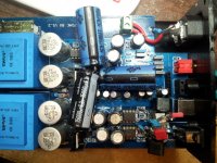
I used NICHICON UVZ1A471MED1TD 470uF caps for the TDA1387 pin 7 mod, originally intending to install them all below the board. I found that the caps have to be absolutely flush against the PCB to allow the unit to be installed in the stock case (as has been previously pointed out ;-), and I couldn't trim the opamp socket pins down enough. I ended up with a hybrid below/above board solution - the ones on top got a bit messy, but it works.
Looks good to me! I like your hybrid approach, actually. Putting all the pin7 electrolytics on top takes up a lot of room and makes the board harder to work with, in my opinion. Plus I found it tedious to solder directly to the tda1387 pins.
It's a shame the PCB doesn't have mounting holes; that would make moving it to a bigger case so much easier. Off and on, I've tried to find some kind of "clamping" standoff to use with this board, so I could move it to a bigger case. Having tall standoffs and moving to a bigger case would make all the mods easier and cleaner I think. Plus, if you ever decide to do the next-gen mods, I don't think there's any way all that additional circuitry will fit inside the stock case.
I also needed to accommodate my USB module, which complicated things slightly. As an aside, the L108 USB module works fine with my raspberry pi and volumio.
If I'm not mistaken, I think the Raspberry Pi can output I2S directly. If you can keep the wire lengths short enough, you could bypass the digital input circuit completely and run I2S straight from the RPi to the tda1387 pins. I did something like that with my first board: soldered three wires directly to the first tda1387 pins (i.e. the I2S pins), and on the other end connected to an Amanero. The Amanero is of course a USB-to-I2S device, but in your case, you just connect directly to the RPi.
Just an idea. 🙂
I used a NICHICON UVR1C103MHD 10000uF cap for the digital supply. These are 35.5mm tall, and even when installed flush to the PCB in replacement of the stock cap, only just fits into the stock case. Similarly with the analogue decoupling caps, I used two NICHICON UPW1V222MHD 2200 uF units. The spacing of the original caps doesn't allow these replacements to be installed flush to the pcb, so they're also a tight squeeze to get back into the case.
Yup, I put electrical tape on the inside of the case where I thought there was any chance of components touching it. I don't want any accidental shorts!
Overall it's been fun learning, fun making the mods, and the improvement to the sound has been significant. Just wish I had a stock unit to compare it against!
I just picked up another stock unit from Cart100 (I may have a compulsion). Anyway, I hooked up the new one, completely stock, just to make sure it works. I don't claim to have the best ears, but I can hear a pretty clear difference between stock and modded. "Night and day" might be a bit dramatic, but many veils are lifted. 😉
By the way, Cart100 will also custom fit 110v transformers.
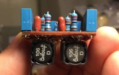
Next step, other than the opamp upgrade, are the CCS and NOS drop filter mods. I'm not overly confident in my air sculpture abilities, so I've been thinking about making a module that plugs into the opamp sockets - I'll post back when I've made some progress.
Opamp socket module - I like that idea! I've often thought that could be done, but no great ideas on the specifics ever came to me.
If you pick reasonable-sized components, the NOS droop filter can be done fairly neatly. Look for Malefoda's pics in this thread (I think they are linked in the Wiki). His NOS droop implementation is nice and tidy. The components I picked are likely overkill, and way too big.
As for the CCS mod: I think my most recent "air sculpture" is half-way decent. I'm sure there's still room for improvement though.
Anyway, thanks again for posting! Glad you're enjoying the DAC.
Did yours come with NE5534? That was the very first thing I did with my (first) tda1387x8, replace the opamps. For me, that alone took the DAC from kind of fatiguing to half-way decent. I never put the NE5534s back in after doing all the other mods...
It did. I've ordered some AD845s, but they're taking a while to arrive. I couldn't resist jumping into all the other mods in the meantime ;-)
Looks good to me! I like your hybrid approach, actually. Putting all the pin7 electrolytics on top takes up a lot of room and makes the board harder to work with, in my opinion. Plus I found it tedious to solder directly to the tda1387 pins.
Thanks & me too - soldering to the below board solder tags was much easier than soldering to the pins, especially when I'd already installed the bigger caps on top of the board.
It's a shame the PCB doesn't have mounting holes; that would make moving it to a bigger case so much easier. Off and on, I've tried to find some kind of "clamping" standoff to use with this board, so I could move it to a bigger case. Having tall standoffs and moving to a bigger case would make all the mods easier and cleaner I think. Plus, if you ever decide to do the next-gen mods, I don't think there's any way all that additional circuitry will fit inside the stock case.
Would it be feasible to drill some mounting holes in the ground planes and use nylon stand offs? There are few areas where there's some exposed PCB real estate where you could do this.
I'm thinking about making a tube I/V stage at some point, so I'll need a bigger case then.
If I'm not mistaken, I think the Raspberry Pi can output I2S directly. If you can keep the wire lengths short enough, you could bypass the digital input circuit completely and run I2S straight from the RPi to the tda1387 pins. I did something like that with my first board: soldered three wires directly to the first tda1387 pins (i.e. the I2S pins), and on the other end connected to an Amanero. The Amanero is of course a USB-to-I2S device, but in your case, you just connect directly to the RPi.
Just an idea. 🙂
Yeah, I've been weighing this one up. I'd still like to use the coax input for my CD player, which precludes direct I2S in as far as I can tell.
Was the Amanero a swap out for another USB module? I'd be interested in how you found any change to the sound. As I understand it, the cheap USB cards are USB to S/PDIF rather than I2S.
Yup, I put electrical tape on the inside of the case where I thought there was any chance of components touching it. I don't want any accidental shorts!
I don't think I've got enough margin for electrical tape! The pin 7 caps are touching the bottom of the case and the 10000uF digital supply cap's touching the top. I've been considering swapping out the stock IEC connector for a fused unit, and installing a ground lug in the case directly. That might require masking off the existing naked PCB track to avoid a ground loop.
By the way, Cart100 will also custom fit 110v transformers.
I'm in Australia, so 220V transformers work for me. Just a note for others purchasing through Cart100: the shipping weight of my unit was 1.235kg (with USB card installed, though that's not going to make much difference.) Cart100 told me it would be 2.6Kg, and charged me extra shipping as a result. On the plus side, it arrived in two days.
Opamp socket module - I like that idea! I've often thought that could be done, but no great ideas on the specifics ever came to me.
I've ordered a bunch of through hole components that are as small as I could find. I'm planning on putting something together on veroboard in the first place - we'll see how it goes.
Cheers,
Jon
Review
There are a lot of DACs on the market today, and they each offer some advantages in capabilities. But when it comes to high performance to cost ratio. This DAC from China I recently purchased and modded is.....Well, Read on. From the outward appearances, this DAC might appear meek and lowly in heart on the surface. But my grand mother, bless her heart, who was an avid reader, used to say "Don't judge a book by its cover". So with that in mind let us turn the page. Even though this DAC does lack some input and output options found in more higher priced DACS. Don't let those options deter you from possibly owning the best performance to cost ratio DAC on the market ever. This is the best bass performance I’d heard to date in-house with this DAC. Some promote the heretical belief that having no DAC is the best DAC, or something like that. Off to the gallows for such reprobates. Because I could not disagree more and can prove it! Playing my favorite tracks held on iTunes, CD Player, Laptop through this insanely cheap but modestly modded DAC. Resulted in a sound that just seemed to relax, extend farther, and fill in just a bit more on the midrange when compared to my other audio sources. I’ve never heard my system sound better. So having said that, I'd like to conclude this review and moreover recognize abraxalito for his outstanding contribution to this DAC project. I did "most" of the mods that abraxalito outlined in his blog. So if you decide to get this DAC or not, do yourself a favor and visit his blog and read up on some of the best information nuggets on DIY Forum. diyAudio - abraxalito
Matt Garmen also did a great job in gathering all the tips and tricks to the DAC mods, along with diagrams, pics, schematics etc. And went forward in making a dedicated wiki to this project. Which BTW is a great time saver for those who want to get down to business of modding. For those who are worried about the 110V power supplies. No problem. Just use Bhiner who is the intermediary with the seller. Tell them you want this built at 115V for USA requirements. And they will take care of the rest. In the coming weeks I plan to visit a few local audiophile stores and do a further comparison testing against some much more expensive DACS.
Attachments

Last edited:
Hey guys,
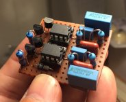
I've made some progress with my CCS and NOS droop filter module - see the attached images. The bad news is I get no sound. I think my problem stems from removing the two SMD resistors and the 220pF cap (aside from the already removed 2N2 feedback cap) between each opamp and the coupling cap. I have no chance of finding the SMD resistors I removed. The silkscreen has them as 75R and 750R - is that right? The silkscreen has the cap at 220pF. What are the functions of these components, and which ones must I replace? From looking back through this thread, it looks like implementations of the NOS droop filter have the two resistors still in place, but not the cap. The SMD resistors seem to be marked with values a lot higher than 75R/750R.
Thanks in advance.
Jon
Attachments
Last edited:
From a quick buzz-out of a spare board, the 75R and 220pF are an RC low pass filter connected to the opamp's output (pin6). They're then connected to the output sockets via the coupling caps which have no silkscreen ID on my board. The 750R is between pin2 and pin6 so that's the feedback resistor. 2n2 goes in parallel with it.
Does this help you restore sound? Its not clear from your pics where your veroboard modules patch in to the original PCB. You look to have coupling caps there so you could just run wires from the output side of those to the output side of the PCB coupling caps.
Does this help you restore sound? Its not clear from your pics where your veroboard modules patch in to the original PCB. You look to have coupling caps there so you could just run wires from the output side of those to the output side of the PCB coupling caps.
Abraxalito, thanks. Closer inspection of my workspace yielded a couple of the resistors. I can't make out the markings, and they measure 300R and 622R. The yellow cap is marked 331 and measures 490pF.
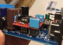
I do have coupling caps on my veroboard, the output side of which connect to the output side of the space on the PCB for coupling caps. There's also a ground rail which I initially forgot to connect, but I'll connect to the PCB ground (just soldered to the track.) I've attached a picture of the mounted board (without ground connection, but showing where the ground track on the PCB has been exposed to accomodate it.)
From what you've said of the components I've removed, it doesn't sound like the absence of the low pass RC filter should prevent sound. I also wouldn't think the absence of the feedback resistor between pin 6 (output) and pin 2 (-ve input) should prevent sound. (Bearing in mind my limited knowledge ;-)
It's late here now. Tomorrow, I'll try replacing the missing components with their through hole counterparts, and see where that gets me.
Thanks again for your help.
Cheers,
Jon
Attachments
Well I learnt something today - I did some reading about how opamps work, and learnt that the feedback resistor is required to reduce the gain to the desired level. Without it, the high gain makes the output effectively either off or on.
I didn't have any 620R resistors on hand, so I've used 670R ones instead, soldering them across pins 2 and 6 of the IC socket below the board. Now I have sound! I'm looking forward to turning it up and having a listen tomorrow.
Thanks again for putting me on the right path, Abraxalito.
Cheers,
Jon
I didn't have any 620R resistors on hand, so I've used 670R ones instead, soldering them across pins 2 and 6 of the IC socket below the board. Now I have sound! I'm looking forward to turning it up and having a listen tomorrow.
Thanks again for putting me on the right path, Abraxalito.
Cheers,
Jon
Ah yes - no feedback resistor means waaaay too much gain, you do indeed get something akin to a digital comparator (albeit rather slower for a typical audio opamp).
The value of that resistor sets the peak output voltage - your array of 8 TDA1387s will deliver a total of 8mA peak to peak. With 670R you'll see 5.4V pk-pk = 1.9VRMS, just a tad short of the standard 2V output.
The value of that resistor sets the peak output voltage - your array of 8 TDA1387s will deliver a total of 8mA peak to peak. With 670R you'll see 5.4V pk-pk = 1.9VRMS, just a tad short of the standard 2V output.
So by my calculations, I need a feedback resistance of 707R to be bang on 2V RMS. I think I might just leave it in its case and listen to it for the time being!
Since 707R isn't very near any standard value (680R would be the closest) I think your plan is the best one, unless you find it won't play loud enough 🙂
Folks:
Burson Audio has a single op-amp replacement for the NE5534s, but at $70 (US) for a pair they ain't cheap (Burson Audio). Mouser sells the AD845 for $10 apiece. I'd consider spending an extra $50 if it was a significant improvement over the alternative. Would this be a ludicrous investment in this case?
Regards,
Scott
The 'supreme sound opamp v5' looks to fit your description. However I couldn't find any technical specification on the website - what's needed in this application is good dynamic performance when slewing. That is decent slew rate and a clean settling transient. So I'd say its taking something of a gamble to spend $70 on a pair of those.
The nonsense Burson spouts about opamps doesn't fill me with much confidence - the more outrageous the marketing, the less I tend to trust any company's products.
The nonsense Burson spouts about opamps doesn't fill me with much confidence - the more outrageous the marketing, the less I tend to trust any company's products.
The 'supreme sound opamp v5' However I couldn't find any technical specification on the website -
https://drive.google.com/file/d/0Bxn23njCr8VCakRUak9PT25yUDA/view?usp=drive_web
Had to use snipping tool, hope you can read it as JPG this is all they give.Thanks but links to Google don't work here. Any chance of attaching it to the post?
Cheers George
Attachments
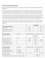
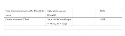
Thanks for doing that. I can read it but I can't make sense of it. For example on the line about 'input offset voltage' it says the units are mV but then it goes on to put the figure down in uV. I can't believe 120uV for a typical offset voltage where the input devices are discrete JFETs - that's as good as an OPA627 where the devices are monolithic and (presumably) trimmed. The bias and offset current specs cannot be true for a JFET input stage as they should be measured in pA, not uA. I've never seen an IC opamp with a bipolar input where the input currents are as high as 180uA - unbelievable.
All in all, not at all inspiring of confidence.
All in all, not at all inspiring of confidence.
Odd that the website mentions a whole list of opamps which can replace the Burson, but they are oddly quiet on which opamps are OK to be replaced by their discrete opamp.
Seeing as no audio IC opamp worth its salt would have an input current within two or three orders of magnitude of the 'v5' its hard to see how serious offset problems can be avoided if the v5 is swapped in. A feedback network impedance of 10k in conjunction with 180uA of input bias current gives almost 2V of input offset.
Seeing as no audio IC opamp worth its salt would have an input current within two or three orders of magnitude of the 'v5' its hard to see how serious offset problems can be avoided if the v5 is swapped in. A feedback network impedance of 10k in conjunction with 180uA of input bias current gives almost 2V of input offset.
- Home
- Source & Line
- Digital Line Level
- TDA1387 x8 DAC: let's check its design, mod it -or not-, play music -or not! :(-