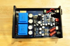
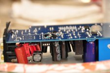
Until yesterday, all my mods have been only on one tda1387 8x unit. Yesterday I spent a little time on a second unit, previously entirely stock (special ordered with 110v transformers). Before I apply the next-gen mods to unit #1, I wanted to have a backup in place. 🙂 Also, unit #1 no longer fits in the case, so I wanted to re-do the easier mods cleanly enough that the case could continue to be used.
I also wanted to use the opportunity to take a couple hopefully decent pictures, with annotations, that others can use as a visual guide to the mods. The mods I did took me about three hours. The hardest part was doing the precision soldering of the caps directly to pin7 of the tda1387 chips. Not really hard so much as tedious.
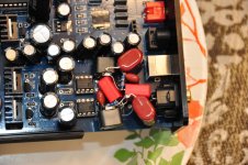
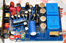
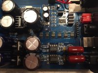
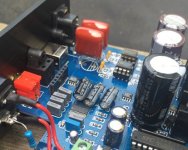
Starting in the upper-left of the annotated picture, going clockwise, the mods I did to this board are as follows:
It's not annotated, but the stock opamps have been replaced. (Those are the 8-pin chips between "2n2 removed" and "analog decoupling".)
The only thing not shown that I did was remove the eight "105" capacitors on the back of the board. These are the stock pin7 capacitors. On my other board, I used the 105 solder pads for bigger electrolytic caps. However, you have to use small caps and carefully trim any solder points on the bottom of the board to get them to lay flat enough to fit the board back in the stock chassis. I also found those caps then interfere with the opamp constant current source mod. So this time around I soldered directly to the pins. It's not hard, but tedious. I would first trim the capacitor leads, then use pliers to form the leads to match the pin layout. I pre-tinned the cap leads, then simply held the cap in place and soldered one lead, adjusted the cap if necessary, and soldered the second.
If you're going to solder directly to the tda1387 IC pins, I suggest doing it after removing other big caps on the board (e.g. digial supply, DC blocking, analog supply), but before replacing the caps, as it gives more room to maneuver. I didn't do this, so at one point I did have to get help from my wife to hold a flashlight for me.
I also wanted to use the opportunity to take a couple hopefully decent pictures, with annotations, that others can use as a visual guide to the mods. The mods I did took me about three hours. The hardest part was doing the precision soldering of the caps directly to pin7 of the tda1387 chips. Not really hard so much as tedious.
Starting in the upper-left of the annotated picture, going clockwise, the mods I did to this board are as follows:
- DC blocking (green) - this isn't in the wiki, but this particular unit came with some cheap electrolytic capacitors for DC-blocking. I replaced them with those great big brown film caps. They are Panasonic polypropylene 4.7uF caps.
- 2n2 removed (red) - "Remove 2n2 Opamp Feedback Capacitors" on the wiki
- Analog Decoupling (yellow) - "Increase Decoupling of Analog Stage" on the wiki
- tda1387 pin7 caps (blue) - "Increase Capacitance Across TDA1387 pin7" on the wiki
- tda1387 supply caps (purple) - "Increase TDA1387 Chip Supply Capacitance" on the wiki
It's not annotated, but the stock opamps have been replaced. (Those are the 8-pin chips between "2n2 removed" and "analog decoupling".)
The only thing not shown that I did was remove the eight "105" capacitors on the back of the board. These are the stock pin7 capacitors. On my other board, I used the 105 solder pads for bigger electrolytic caps. However, you have to use small caps and carefully trim any solder points on the bottom of the board to get them to lay flat enough to fit the board back in the stock chassis. I also found those caps then interfere with the opamp constant current source mod. So this time around I soldered directly to the pins. It's not hard, but tedious. I would first trim the capacitor leads, then use pliers to form the leads to match the pin layout. I pre-tinned the cap leads, then simply held the cap in place and soldered one lead, adjusted the cap if necessary, and soldered the second.
If you're going to solder directly to the tda1387 IC pins, I suggest doing it after removing other big caps on the board (e.g. digial supply, DC blocking, analog supply), but before replacing the caps, as it gives more room to maneuver. I didn't do this, so at one point I did have to get help from my wife to hold a flashlight for me.
Attachments

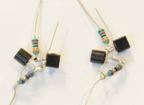
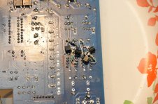
...and here's another constant current source mod, prepped and ready to be soldered to the board. Earlier in the thread I posted pic of my first implementation of this mod, but I think this is a better pic. Better focus, higher resolution. Hopefully useful to someone!
Attachments
At long last here's the schematic (hand drawn as LTSpice's TL431 symbol is really confusing) for the discrete I/V modification.
Implementing the balanced outputs requires four of the BC807s (or BC327s if you're doing this non-SMT) plus associated FBs and 1k1 resistors. Only one TL431, 220uF and set of voltage setting resistors is required though - there's plenty of current available to feed the 3.8V voltage reference to 4 I/V transistors.
Maybe I'm missing something, but looks like you have a 360 ohm resistor in series with a 1.2k ohm... any reason not to use a single 1.5k ohm?
A single 1k5 resistor will give a slightly lower reference voltage (3.75V, 50mV reduced) but should work fine yes.
For the constant current source mod - what happens if opamp pins 6 and 7 are swapped? I.e. the part that is supposed to go to pin 6 actually landed on pin 7, and vice-versa?
Looking back at my first go at the CCS mod, I think I got hit by pin dislexia and swapped those pins...
Looking back at my first go at the CCS mod, I think I got hit by pin dislexia and swapped those pins...
Next-Gen Consolidated Info
I annotated the anti-imaging and class-a buffer circuits. Abraxalito, can you confirm I got these right?
I'm also re-posting some previous pics and circuit schematics, in the interest of convenience (Abraxalito, I hope you don't mind me re-posting your pics). Eventually I'll add this to the wiki...
In order, the pics are:
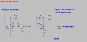
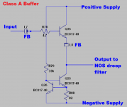
- Anti-Imaging Filter Annotated Schematic
- AI Filter Pic
- Class A Buffer Annotated Schematic
- I/V Circuit
- I/V Pic
Attachments

Next-Gen Consolidated Info Part 2
OK, I attempted to draw out one big circuit (sort of) for the next-gen mods. Abraxalito, if you're willing, would you mind taking a look at this to ensure I got it right?
I drew out the I/V stage literally, but for the following circuits (anti-imaging filter, buffer, droop filter), I only drew one instance. I believe there would need to be four instances of these circuits, one each for R+, R-, L+, L-.
I am doing this assuming balanced output.
If I got this right, I'll draw up a BOM.
Note: I posted both in JPG and PDF format, content is the same otherwise.
Attachments
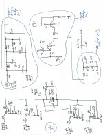
I had a look over the schematic - its correct assuming you're not using an output trafo. Looks like you're going balanced out to an XLR.
As regards your question about the CCS mod - that's the one biassing the opamp into classA is it? If so then putting the CCS onto pin6 of the opamp won't bias it into classA, rather it will introduce a significant positive voltage offset at the output (pin7). The TDA1387s are already biassing the opamp's output negatively so it might just undo this effect - I have such mods already on my version of the DAC.
As regards your question about the CCS mod - that's the one biassing the opamp into classA is it? If so then putting the CCS onto pin6 of the opamp won't bias it into classA, rather it will introduce a significant positive voltage offset at the output (pin7). The TDA1387s are already biassing the opamp's output negatively so it might just undo this effect - I have such mods already on my version of the DAC.
So indeed, on board #1, I flopped pin6 and pin7 for the opamp CCS mod. Now fixed.
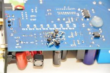
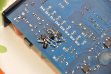
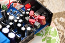
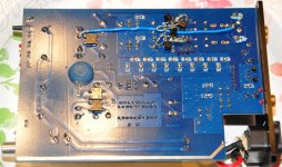
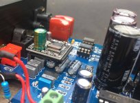
Here are some pics of CCS mod on board #2. This was a bit challenging to keep close enough to the board that I could still slide the PCB in the case. I almost ordered some SMD components to make it easier, but in the end, I think it's a decent solder job.
Just to be safe I coated the bottom of the chassis with electrical tape, just in case anything hits on it. But as far as I can tell, it's not touching the case. Better safe than sorry, either way.
If you look closely, you'll see I wrote the pin numbers on the bottom of the PCB this time around. 🙂
Attachments

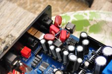
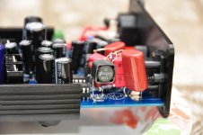
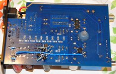
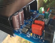
And here are some pics of the NOS droop filter on board #2. I used great big Panasonic polypropylene 4.7uF caps for DC blocking. This made it a challenge to actually fit all the components of the droop filter in the space, and leave room for opamp rolling. I think I pulled it off.
I think Malefoda's filter implementation is much neater. But I'm using much bigger (physically) caps and was afraid they'd give me problems sliding the PCB back into the chassis if I put them on the bottom.
Another exercise in "air sculptures" for those who enjoy the pics!
I think Malefoda's filter implementation is much neater. But I'm using much bigger (physically) caps and was afraid they'd give me problems sliding the PCB back into the chassis if I put them on the bottom.
Another exercise in "air sculptures" for those who enjoy the pics!
Attachments

So how's the temperature of the AD845s now? I remembered after posting this mod that you'd not decreased their supply yet so they must be getting quite toasty with the extra 8mA or so of bias? Oh and any change to how it sounds?
FWIW, I found my IR temperature gun! After well over 12 hours of continuous playing, the top of the AD845 package was about 115 degrees F which is about 46 degrees C. Looks like the max operating temp for the AD845 is 70 degrees C, so I'd say I'm safe.
This is in the open air, since this will no longer fit in the stock case.
Re-answering this question, since the first answer was based on an incorrect implementation of the CCS. Also, board #2 fits in the case so I can test with the board running inside the case.
Anyway: after nearly 23 hours of continuous operation, enclosed within the chassis, the AD845s don't appear to get any hotter than 52 deg C (at least that's the package temperature according to my IR temp gun). The case is warm to the touch, but not hot, that reads about 35 deg C. Ambient room temperature is about 25 deg C.
Looks like I'm still plenty safe.
This thread is long overdue for a bump! 🙂
I put together a BOM for the next-gen mods. This is, barring any error on my part, all the parts needed to assemble the hand-drawn complete circuit I posted recently. Note my approach is slightly different than Abraxalito's, as I plan for balanced (XLR) output, rather than single-ended (RCA).
I don't have enough experience to know the ideal components for each case, so likely this is a sub-optimal BOM. Some notes on my thought process, feel free to criticize:
Here is the Google Docs link (read-only). If you're willing to help refine this, PM me and I'll give you write access.
If anyone has the time and patience to check this, that would be sincerely appreciated. As I said, I'm sure my selections are likely sub-optimal in one or more dimensions (cost, tolerance, size, composition, etc).
I put together a BOM for the next-gen mods. This is, barring any error on my part, all the parts needed to assemble the hand-drawn complete circuit I posted recently. Note my approach is slightly different than Abraxalito's, as I plan for balanced (XLR) output, rather than single-ended (RCA).
I don't have enough experience to know the ideal components for each case, so likely this is a sub-optimal BOM. Some notes on my thought process, feel free to criticize:
- I generally preferred through-hole components. Personally, I intend to implement this using turret or "prototyping" boards (like Abraxalito does), where SMD would work, but I thought the through-hole components are more "general" if someone wants to do point-to-point.
- I tried to find parts that were available on both Mouser and DigiKey. Not sure this was worth the significant amount of extra effort. Also, there are cheaper parts if you allow for components only available on one vendor or the other. But I thought that if they were available on both of the major USA vendors, then they'd be relatively easy to find for non-USA folks.
- I don't know what tolerances are appropriate for this application... I figure lower tolerances never hurt, except for the expense. So I tended towards 1% resistors, and 5% or better capacitors.
- I'm also not sure what composition is best for the components... I generally chose metal film for the resistors, and film for the caps (except for the 220uF I/V cap, that's an electrolytic). A couple resistors are carbon film, because that's all I could find in the required value.
- I created this in Google Docs, and exported to both Excel and OpenDocument (OpenOffice/LibreOffice) formats. Those file formats are contained in the .zip file (this forum won't let me attach these formats directly). I also exported a PDF.
- For the anti-imaging filter, neither Mouser nor DigiKey had the 1.1nF or 17.3nF (or even 17.0nF) film caps in stock. Not sure what to do there.
Here is the Google Docs link (read-only). If you're willing to help refine this, PM me and I'll give you write access.
If anyone has the time and patience to check this, that would be sincerely appreciated. As I said, I'm sure my selections are likely sub-optimal in one or more dimensions (cost, tolerance, size, composition, etc).
Attachments
Good work matt - I've downloaded the .pdf file and will work on the anti-imaging filter to resolve those rather 'weird' cap values. In China, Google's blocked so I'll make a text file of the amendments.
Pics, fancy caps, more questions...
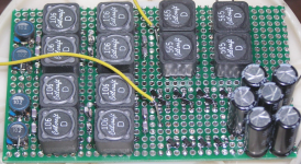
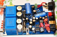
Here's a few more pics of my second board, including the bottom.
One thing I've noticed with this DAC is that if I turn the volume all the way up on my amp, without any music playing, there is a slight hum/buzz coming through the speakers. Last night I upped the RCA grounding resistors from 10k to 1M (see item 3 on 'Braxy's blog), and that helped quite a bit, but it's still there. Anyone have any thoughts on how I can further reduce this? It's not a real problem, since my listening levels are so far away from max volume, but it's starting to bother me because I know it's there. I have my amp's gain set pretty low too (20 or 26 dB), so I suspect the problem would be more pronounced with higher gain. I'm using optical input so it's definitely not coming from that.
Abraxalito, questions from your blog:
Does it still make sense to put the X7Rs across the opamp supply pins with the CCS in place? And when you say "4 per chip", did you mean two per chip? Which pins do those X7Rs go across?
Another random update: I emailed that Cart100 place, they will sell a 110v version direct.
Also, any update on the TDA1545 DAC you hinted at over here?
Here's a few more pics of my second board, including the bottom.
One thing I've noticed with this DAC is that if I turn the volume all the way up on my amp, without any music playing, there is a slight hum/buzz coming through the speakers. Last night I upped the RCA grounding resistors from 10k to 1M (see item 3 on 'Braxy's blog), and that helped quite a bit, but it's still there. Anyone have any thoughts on how I can further reduce this? It's not a real problem, since my listening levels are so far away from max volume, but it's starting to bother me because I know it's there. I have my amp's gain set pretty low too (20 or 26 dB), so I suspect the problem would be more pronounced with higher gain. I'm using optical input so it's definitely not coming from that.
Abraxalito, questions from your blog:
2) Reduce the supply voltage to the output opamps so X7R caps can be used between the rails to good effect. Lower voltage on X7Rs means higher capacitance so really there should only be enough supply rail volts to achieve the desired output level (2VRMS). Increase the resistors feeding the shunts (add 100R in series with existing 150R).
3) Fit 10uF/25V 1206 X7Rs across both opamp supply pins (4 per chip). Remove the 4 film caps doing decoupling. Change 10k output grounding resistors to 1M.
Does it still make sense to put the X7Rs across the opamp supply pins with the CCS in place? And when you say "4 per chip", did you mean two per chip? Which pins do those X7Rs go across?
Another random update: I emailed that Cart100 place, they will sell a 110v version direct.
Also, any update on the TDA1545 DAC you hinted at over here?
Attachments
Hi matt - not ignoring your questions or this thread - I'm currently engaged in a couple of new designs which are more exciting to develop than they are to write about. Hence my silence for the time being - they're both relevant to DACs and have the potential to reduce the size (caps, inductors) if they turn out to sound good enough. Which means possibly a more portable DAC 🙂
Quick answers to some of your questions - yes when I wrote 4 I meant 4. The supply pins are 4 and 7 for single opamps. Having better decoupling is still desirable even when the output's CCS loaded.
Quick answers to some of your questions - yes when I wrote 4 I meant 4. The supply pins are 4 and 7 for single opamps. Having better decoupling is still desirable even when the output's CCS loaded.
Last edited:
One thing I've noticed with this DAC is that if I turn the volume all the way up on my amp, without any music playing, there is a slight hum/buzz coming through the speakers. Last night I upped the RCA grounding resistors from 10k to 1M (see item 3 on 'Braxy's blog), and that helped quite a bit, but it's still there. Anyone have any thoughts on how I can further reduce this?
I don't turn up the volume on my set up without any music playing so this isn't exactly an apples-apples comparison but I haven't noticed any hum issues at all with my setup. It could well be because I have the transformers located physically distant from the circuit board now. EI core transformers are leaky of magnetic flux and having them close to circuit boards carrying low-level signals isn't really recommended. In my headphone amp which I modded to include output transformers (also EI core) I get hum in one channel due to the physical proximity of the OPT to the mains trafo. The distance between the two trafos being over 10cm.
A possible solution (other than physically moving the trafos) is reducing the flux in the trafo - this could be achieved by using 220V primary trafos on 110V. The output regulators would have to be set around half the original voltage - but I reckon that's about optimum for this anyway.
Also, any update on the TDA1545 DAC you hinted at over here?
I've now had some listening to a new (for me) design of active filter, using a variation on the classA buffers I've posted up on this thread. I posted an introduction to this on my blog yesterday. From the listening so far, its definitely worth persuing so I'll try using a steep-slope active filter in place of the inductor filters I've shared on this thread. The active filter uses cheap components so should work out cheaper than Coilcraft inductors, also less bulky and lighter for those wishing to build portable DACs. I also have a discrete I/V converter in the works - primarily being designed to achieve a much lower input impedance at the DAC's output than the single transistor stage I've posted here.
A single common-base transistor gives an input impedance (to its emitter) depending on the current flowing - typically in the region of 2mA it'll be around 10-15ohms. My current feedback stage simulates on LTSpice below 100mohms. I've not yet listened to it, at present working on the dynamic response (curing overshoot on step input waveforms). I feel low input impedance is important to getting good 'snap' - I currently am biassing my single transistor stage with CCSs (3mA or so) to increase the working current and hence lowering the input impedance. Its a worthwhile SQ improvement - I'm hoping the CFB stage will build on that enhancement.
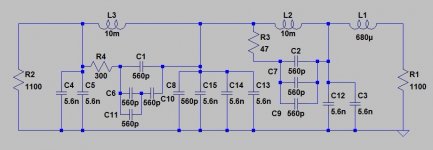
Simplified BOM anti-imaging filter
I went over to Mouser just now to look at the pricing on SMT ceramics. Typically prices for 100+ are about a quarter of the 1offs. Hence it makes some sense to avoid cap values where only two are needed. In that vein, here's a cost-reduced version of the filter which uses only two capacitor values - 5.6nF and 560pF. 0603 560pFs are cheaper than 0805 but if your eyesight or hand steadiness isn't up to such small packages then 0805 will be fine. I'd just suggest go for 5% or better and steer clear of the lower voltage parts - go for 25V working or higher. TDK 0805 looks to be the best bet for the 5.6nFs.
I went over to Mouser just now to look at the pricing on SMT ceramics. Typically prices for 100+ are about a quarter of the 1offs. Hence it makes some sense to avoid cap values where only two are needed. In that vein, here's a cost-reduced version of the filter which uses only two capacitor values - 5.6nF and 560pF. 0603 560pFs are cheaper than 0805 but if your eyesight or hand steadiness isn't up to such small packages then 0805 will be fine. I'd just suggest go for 5% or better and steer clear of the lower voltage parts - go for 25V working or higher. TDK 0805 looks to be the best bet for the 5.6nFs.
Attachments
More information on the TDA1545 DAC
A short status update on the TDA1545 DAC design - I now have a basic prototype working with the following structure -
- I2S to EIAJ conversion (3 74HC logic chips)
- balanced TDA1545A (currently only using one phase for output)
- discrete I/V stage (see my latest blog post for schematic)
- discrete 8th order filtering - 6 for anti-imaging, 2 for NOS droop correction
One advantage of the TDA1545 (besides the lower current draw and potentially higher current output) is that its reference input doesn't need a large-ish electrolytic cap for best bass. At present I just have a current source feeding pin7 but I'll probably experiment with RC too.
Having an all-discrete back end for the DAC means in theory I won't need any voltage amplification before feeding speakers, just diamond buffers. The I/V stage can be configured to provide sufficient voltage gain and the filtering should be happy to run with high voltage swings (provided the transistors and caps are rated appropriately).
Hi guys,
I recently received one of these from Cart100, and have tackled some of the mods in the wiki. Thanks to all the excellent information in this thread and on the wiki, it's mostly been pretty easy.
My board came with axial 'lytics for the output coupling caps, so I replaced those with 2u2 film caps, although all I had to hand was 100V.
I'm still waiting on the opamps to arrive, so haven't done that mod yet.
I used NICHICON UVZ1A471MED1TD 470uF caps for the TDA1387 pin 7 mod, originally intending to install them all below the board. I found that the caps have to be absolutely flush against the PCB to allow the unit to be installed in the stock case (as has been previously pointed out ;-), and I couldn't trim the opamp socket pins down enough. I ended up with a hybrid below/above board solution - the ones on top got a bit messy, but it works. I also needed to accommodate my USB module, which complicated things slightly. As an aside, the L108 USB module works fine with my raspberry pi and volumio.
I used a NICHICON UVR1C103MHD 10000uF cap for the digital supply. These are 35.5mm tall, and even when installed flush to the PCB in replacement of the stock cap, only just fits into the stock case. Similarly with the analogue decoupling caps, I used two NICHICON UPW1V222MHD 2200 uF units. The spacing of the original caps doesn't allow these replacements to be installed flush to the pcb, so they're also a tight squeeze to get back into the case.
Overall it's been fun learning, fun making the mods, and the improvement to the sound has been significant. Just wish I had a stock unit to compare it against!
Next step, other than the opamp upgrade, are the CCS and NOS drop filter mods. I'm not overly confident in my air sculpture abilities, so I've been thinking about making a module that plugs into the opamp sockets - I'll post back when I've made some progress.
Cheers,
Jon
Attachments
Last edited:
- Home
- Source & Line
- Digital Line Level
- TDA1387 x8 DAC: let's check its design, mod it -or not-, play music -or not! :(-