Update - December 14, 2018
Since starting this thread, it's gone in a lot of different directions and much ground has been covered. So with this edit, I'm trying to provide a table of contents of sorts, mostly highlighting all the different designs that have been presented, and highlighting other particularly interesting sub-threads along the way.
1. Front-end v1.0
2. Single-ended RPI HAT v1.2
3. Balanced RPI HAT v3.0
4. Abraxalito's lingDAC
5. Front-end v2.0
6. Schematic for a barebones tda1387 implementation
7. RPI DAC Front-End v1.0.0
8. RPI DAC HAT (also standalone) single-ended v1.6
Original Post - October 12, 2017
Based on this tda1387x8 thread, I developed a bit of an affinity for the sound of the old tda1387 DAC chip. The topic of the linked thread was a standalone DAC that had eight of those chips paralleled; it also had optical or coaxial SPDIF input (and optional USB input), single-ended output, and a basic op-amp IV circuit. Some fairly simple mods (detailed in the wiki) made it go from just OK to quite engaging and enjoyable (at least to my ears).
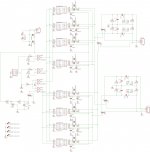
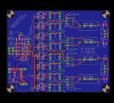
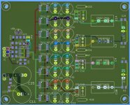
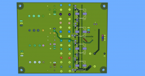
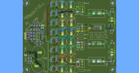
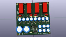
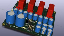
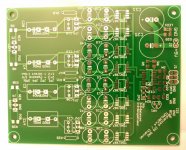
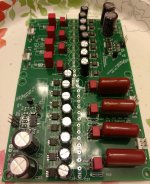
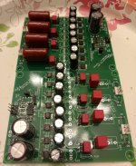
Taking all the lessons learned from modding that DAC, and some of my personal goals, I wanted to create a basic "front end" DAC with these chips. Attached are images of what I came up with, with the following features/goals in mind:
I think this is pretty flexible: you could get up and running quickly with only one tda1387 chip and passive IV; or you could go crazy and max out all the caps, stack multiple tda1387 chips, and implement the fanciest IV scheme you can imagine. Or anything in-between!
Also, the package and pinout for the tda1543 is the same as the tda1387. I see no reason why this board couldn't be used for the tda1543 as well. Edit: this is incorrect, the package sizes for tda1543 and tda1387 are different.
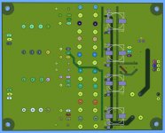
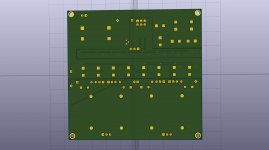
Note: I only just now rendered the gerber files, and looking at the bottom of the board, I see the big pin5 cap footprints interfere with the little pin5 SMD caps. Should be easy enough to fix.
Happy to hear any comments, critiques, suggestions.
Since starting this thread, it's gone in a lot of different directions and much ground has been covered. So with this edit, I'm trying to provide a table of contents of sorts, mostly highlighting all the different designs that have been presented, and highlighting other particularly interesting sub-threads along the way.
1. Front-end v1.0
- I did this in Eagle, which I've long since abandoned in favor of KiCad
- Built and tested, works, but no longer maintained
- Gerbers in post #16
- pics of test builds in post #19
- BOM in post #45
2. Single-ended RPI HAT v1.2
- v1.0 had the wrong tda1387 footprint, unusable
- On v1.1 I screwed up the Gerber export, resulting in boards with no ground plane
- pics of test builds in post #58
- BOM, Gerbers, and KiCad files in post #66 (schematic in post #68)
3. Balanced RPI HAT v3.0
- Not sure why the first boards are v3.0
- Known bug with tl431 pin designations
- pics of test builds in post #89
4. Abraxalito's lingDAC
- Much more sophisticated tda1387 implementation
- See his Hackaday page
- diyAudio thread
5. Front-end v2.0
- Same concept as v1.0, but complete re-design in KiCad instead of Eagle
- I never actually had this design fabricated, so it's untested
- BOM, Schematic, Gerbers, KiCad files in post #196
6. Schematic for a barebones tda1387 implementation
- Suitable for breadboard or point-to-point implementation
- Intent is to be cheap, quick and relatively easy to build, even for beginners
- Post #297
7. RPI DAC Front-End v1.0.0
- Intended to capture some of the concepts of the Front-End boards, but in a form factor that is suitable for use with a Raspberry Pi (but can also be used standalone)
- Build pics in post #236
- post #402 has schematic, Gerbers, BOM and KiCad files
8. RPI DAC HAT (also standalone) single-ended v1.6
- Uses MAX6071 precision voltage reference instead of tl431 for I/V transistor base voltage (2.5v)
- Other small tweaks
- See post #409 for schematic, Gerberes, BOM, KiCad files, and prototype build pics
Original Post - October 12, 2017
Based on this tda1387x8 thread, I developed a bit of an affinity for the sound of the old tda1387 DAC chip. The topic of the linked thread was a standalone DAC that had eight of those chips paralleled; it also had optical or coaxial SPDIF input (and optional USB input), single-ended output, and a basic op-amp IV circuit. Some fairly simple mods (detailed in the wiki) made it go from just OK to quite engaging and enjoyable (at least to my ears).
Taking all the lessons learned from modding that DAC, and some of my personal goals, I wanted to create a basic "front end" DAC with these chips. Attached are images of what I came up with, with the following features/goals in mind:
- I2S input: use an SBC, SPDIF receiver, XMOS, etc.
- User-supplied power supply: be as cheap/simple or fancy as you want.
- Adding capacitance to pin7 of the tda1387 chip was one of the biggest gains in sound quality improvement (particularly bass); this board has room for 2x 8mm pin7 caps per tda1387 chip.
- Solder pads on the bottom of the board for up to four 10mm caps for the tda1387 chip's VDD supply (pin5); this allows tda1387 chips to be "stacked", boosting current output (e.g. this could be made into a headphone amp).
- Uses a logic inverter chip (74HC86) to optionally invert the I2s DATA signal to half the tda1387 chips. This allows for balanced output. Note this is optional, a jumper setting allows the user to select single-ended output mode (i.e. don't invert the data).
- Has jumper pins for user-selectable simple passive I/V, or direct current-output for a custom I/V scheme.
I think this is pretty flexible: you could get up and running quickly with only one tda1387 chip and passive IV; or you could go crazy and max out all the caps, stack multiple tda1387 chips, and implement the fanciest IV scheme you can imagine. Or anything in-between!
Also, the package and pinout for the tda1543 is the same as the tda1387. I see no reason why this board couldn't be used for the tda1543 as well. Edit: this is incorrect, the package sizes for tda1543 and tda1387 are different.
Note: I only just now rendered the gerber files, and looking at the bottom of the board, I see the big pin5 cap footprints interfere with the little pin5 SMD caps. Should be easy enough to fix.
Happy to hear any comments, critiques, suggestions.
Attachments
Last edited:
Hope this isn't too much of a 'fly in the ointment' but the SMT package of TDA1543 is rather different (SO16 wide) from that of TDA1387 (SO8). As a result I reckon it would be very tricky to try to fit them here. The pin orderings and positions are the same though, not that that's too much consolation.
Hope this isn't too much of a 'fly in the ointment' but the SMT package of TDA1543 is rather different (SO16 wide) from that of TDA1387 (SO8). As a result I reckon it would be very tricky to try to fit them here. The pin orderings and positions are the same though, not that that's too much consolation.
D'oh, I just saw that the pinouts were the same, and didn't realize that the package size was different. No matter though, tda1543 compatibility wasn't an explicit design goal---I just (wrongly) assumed it was a useful side-effect.
Although I suppose an enterprising individual could get creative with little jumper wires and the soldering iron and make it work. That person ain't me! 😉
In hindsight, perhaps designing this for tda1543 from the start would have been the smarter move. It would be much easier to fit the tda1387 into the tda1543 footprint, rather than the other way around. All think about doing that, as I'm working on learning KiCAD (in place of Eagle), and that would be a good exercise. Available time will be the main factor though.
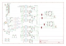
At any rate, here's the latest and greatest. Passes all automatic checks, and I don't see any obvious errors. Thinking of submitting to the fab house.
At any rate, here's the latest and greatest. Passes all automatic checks, and I don't see any obvious errors. Thinking of submitting to the fab house.
Attachments

FYI, here are some useful diyAudio links on the tda1387 chip, for anyone who might be interested:
TDA1387 x8 DAC: let's check its design, mod it -or not-, play music -or not! 🙁-
TDA1387 X8 NOS DAC (Wiki)
TDA1387 continuous calibration dac
Improving passive I/V for Pi dac 8 x TDA1387
TDA1387 x8 DAC: let's check its design, mod it -or not-, play music -or not! 🙁-
TDA1387 X8 NOS DAC (Wiki)
TDA1387 continuous calibration dac
Improving passive I/V for Pi dac 8 x TDA1387
First, a couple more relevant links that might be interesting:
Dirty Dac, 16x TDA1387 dual mono symmetrical.
help me with my dac design?
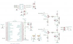
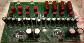
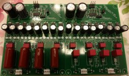
Second, I've re-drawn this board using KiCAD. The built-in 3D viewer alone is worth the price of admission (KiCAD is free/open source, so the only cost is the learning time).
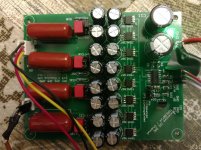
Anyway, here's a "version 2" of the board. Or maybe "version 1.1" is more appropriate, since it's only a minor tweak on the original design. Only one pin7 cap per tda1387 chip, but with a bigger (10mm) footprint. Also, all components are on the top of the board. And I created three separate ground planes, one each for digital, analog, and power.
Dirty Dac, 16x TDA1387 dual mono symmetrical.
help me with my dac design?
Second, I've re-drawn this board using KiCAD. The built-in 3D viewer alone is worth the price of admission (KiCAD is free/open source, so the only cost is the learning time).
Anyway, here's a "version 2" of the board. Or maybe "version 1.1" is more appropriate, since it's only a minor tweak on the original design. Only one pin7 cap per tda1387 chip, but with a bigger (10mm) footprint. Also, all components are on the top of the board. And I created three separate ground planes, one each for digital, analog, and power.
Attachments
Nice job Matt - turning this thread into a TDA1387 resource. I am looking forward to building a DAC from one of your PCBs...
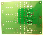
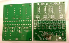
I received the boards for the first design (haven't submitted "v2" yet). I had these made by Elecrow. They happened to be having a sale when I submitted: $4.90 for 10 boards (up to 10x10), and $4.80 air mail shipping to USA. Under $10 for 10 boards---and they actually sent me 13 boards!
If anyone is interested, I probably only want to build one or two of these at most. So if you cover shipping, I'll give away the board itself. If you're in the Chicago area, stop by and grab a couple!
If anyone is interested, I probably only want to build one or two of these at most. So if you cover shipping, I'll give away the board itself. If you're in the Chicago area, stop by and grab a couple!
Attachments
Although I've got five or so in my bin, I've used only a single TDA1387 in my experiments (all in Philips CDP that orig. used a 1543).
I know much of the romance with this DAC chip began with the parallel x 8 design orig. offered a few years ago.
How much sonic benefits actually (subjectively) accrue when more than one TDA1387 are stacked?
I'm assuming parallel x 8 is some sort of sweet-spot?
I know much of the romance with this DAC chip began with the parallel x 8 design orig. offered a few years ago.
How much sonic benefits actually (subjectively) accrue when more than one TDA1387 are stacked?
I'm assuming parallel x 8 is some sort of sweet-spot?
A couple of thou!!!!!!!!!!!
😱
Brax is gonna need a couple thou. Maybe less than 1k if Brax really maxes out on all the 1387 footprints on Matt's boards.I am looking forward to building a DAC from one of your PCBs...
😱
How much sonic benefits actually (subjectively) accrue when more than one TDA1387 are stacked?
I've not noticed there being sonic benefits from paralleling chips. Rather paralleling gives more flexibility over design of the I/V stage - for example it allows lower output impedance by virtue of switching higher currents. The 1mA total swing of a single chip is low by DAC standards - the lowest of any multibit DAC that I'm aware of.
I know much of the romance with this DAC chip began with the parallel x 8 design orig. offered a few years ago.
That was, quite literally, my inspiration for this design. Romance is an apt word. I was underwhelmed with my first foray into NOS DACs, but that x8 DAC changed my mind. But there comes a point where it just gets messy to continue to hack on the x8 board. So my intent here is to create a modular "framework" for folks wanting to play with the tda1387 chip. Folks might be limited to Richard and I, but I'm OK with that! At the end of the day, I simply enjoy designing PCBs, and ever since I first took a soldering iron to that x8 DAC, I've wanted to design my own tda1387 board.
How much sonic benefits actually (subjectively) accrue when more than one TDA1387 are stacked? I'm assuming parallel x 8 is some sort of sweet-spot?
Dunno. I used eight only because that's what the x8 DAC used. But you do need at least two chips if you want balanced output (which I do). Other than wasting PCB space, there's no reason you have to populate all eight chips. The intent is to be flexible, to allow for relatively easy trial-and-error.
TDA1387 Dragonfly
1387's low power consumption makes it ripe for, say, an iPhone dongle.
If you/someone were to design a thumbnail-sized PCB (form actor: Dragonfly), you may get more interest.
Here on DIYA, I think I have seen a few TDA1387 projects (??) with pretty small form factors.
Hmmm...I've wanted to design my own tda1387 board.
1387's low power consumption makes it ripe for, say, an iPhone dongle.
If you/someone were to design a thumbnail-sized PCB (form actor: Dragonfly), you may get more interest.
Here on DIYA, I think I have seen a few TDA1387 projects (??) with pretty small form factors.
Ill take two boards if u have them matt
I'll take a board if still available 🙂
Nice of you to offer them for just shipping cost.
Yup, still have all 13 boards! Only just now ordered the parts to do the build up. I need only two or three at most, the rest are free to whoever wants them.
However, nige2000 and Mayday, based on shipping costs, I suspect it might be cheaper for you just to order your own boards straight from Elecrow. When I placed my order, it was $5 for the boards and $5 shipping from China to the USA. I'm assuming Elecrow shipping to your countries is the same as it is for the USA.
Some quick Internet research suggests $20 might be as cheap as I can get to ship to Ireland or Sweden.
Not trying to discourage you, just don't want you to waste money. At a minimum, you might want to wait until I build up the first one to make sure I didn't make any mistakes!
I attached the Gerber files I sent to Elecrow, if you want to go that route.
Attachments
Wow, that's alot to send one PCB. I understand why you wanted to mention that.
I'll hold off for now.
Thanks for the heads up 🙂
I'll hold off for now.
Thanks for the heads up 🙂
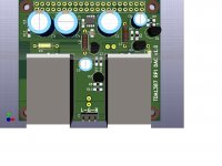
Here's another spin on the tda1387 theme: a Raspberry Pi HAT DAC. This was inspired by didiet78's tda1387 DAC for Orange Pi.
Attachments
Hope they work!
Spent way longer than I expected soldering a couple of these up. For the ICs and SMD components, I used solder paste and a skillet. I used too much solder paste, so ended up spending way too much time fixing solder bridges. Lesson learned: less is more with ICs and solder paste. Very frustrating.
Anyway... here's to hoping they actually work!
Attachments
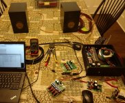
They actually work!
Playing music as I type this.
The first test with the first board was a total failure: sound was complete noise. Turns out I missed a solder bridge across two pins of the HC86 logic chip. Before fixing that, I tried the second board: I got something recognizable as music, but still fairly distorted. I removed the solder bridge on the first board, and it was now the better sounding of the two boards, but still not perfect.
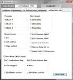
For I2S source, I'm using an Amanero (USB to I2S) device that I've had now for a couple years. I had to tweak the settings a bit. The sound cleaned up further with the right settings; see attached screenshot.
There was still a bit of "fuzz" on both boards, so I used a flashlight to look more closely at the tda1387 IC pins. Yup, more solder bridges (or at least partial ones). Thank goodness for copper solder wick!
Now they are definitely both playing pretty clean as far as I can tell.
The laptop didn't have ASIO drivers set up, so I installed that Foobar plugin. That seemed to clean things up a tiny bit too (or maybe my imagination). But I definitely wasn't "bit perfect" prior to that, as I could still hear Windows system sounds layered on top of the music. Now those are gone, Foobar has exclusive control of the Amanero.
I went ahead and added another eight pin7 caps to one of the boards, and installed the pin5 polymer caps on the board's bottom. Can't really tell any difference. But then again, I'm still in a pure test config.
Main lesson here, for me anyway, is to use the solder paste very sparingly. I'm certain I spent more time cleaning solder bridges than if I'd just hand-soldered the SMD stuff in the first place.
Thus far all tests have been with single-ended output. Next step is to solder up some XLR connectors so I can do a test of the balanced output.
Playing music as I type this.
The first test with the first board was a total failure: sound was complete noise. Turns out I missed a solder bridge across two pins of the HC86 logic chip. Before fixing that, I tried the second board: I got something recognizable as music, but still fairly distorted. I removed the solder bridge on the first board, and it was now the better sounding of the two boards, but still not perfect.
For I2S source, I'm using an Amanero (USB to I2S) device that I've had now for a couple years. I had to tweak the settings a bit. The sound cleaned up further with the right settings; see attached screenshot.
There was still a bit of "fuzz" on both boards, so I used a flashlight to look more closely at the tda1387 IC pins. Yup, more solder bridges (or at least partial ones). Thank goodness for copper solder wick!
Now they are definitely both playing pretty clean as far as I can tell.
The laptop didn't have ASIO drivers set up, so I installed that Foobar plugin. That seemed to clean things up a tiny bit too (or maybe my imagination). But I definitely wasn't "bit perfect" prior to that, as I could still hear Windows system sounds layered on top of the music. Now those are gone, Foobar has exclusive control of the Amanero.
I went ahead and added another eight pin7 caps to one of the boards, and installed the pin5 polymer caps on the board's bottom. Can't really tell any difference. But then again, I'm still in a pure test config.
Main lesson here, for me anyway, is to use the solder paste very sparingly. I'm certain I spent more time cleaning solder bridges than if I'd just hand-soldered the SMD stuff in the first place.
Thus far all tests have been with single-ended output. Next step is to solder up some XLR connectors so I can do a test of the balanced output.
Attachments
- Home
- Source & Line
- Digital Line Level
- tda1387 dac pcb "front end"