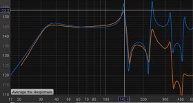
This shows the predicted response of the 15TBX100-4 in the horn, original size (grey) and the width reduced by 2 inches (red). The change is very minor. I doubt anyone would notice the difference. This also shows that that particular design is probably not the best match for the 15TBX100-4

I combined both sheets into one 🙂Uh?
I only see the same models you had before
Where is the lonely TH15 spreadsheet?
If someone wants to, for example, make the plan narrower in width in order to be able to adapt it to their desired dimensions

Well, I figured out why - my sim was a little slimmer than the Lonely TH15 Pro, LOL. Here's the Hornresp sim that the BOXPLAN workbook produces when the correct box size is entered:Almost done ...! The optimization routine is now working. Just a bit of cleaning up to do, but the workbook is working ...
Note: I've entered the external dimensions of the Lonely TH15 Pro, set the workbook to assume 15 cm ply, and adjusted the step in expansion and mouth ratio size to produce a result where the mouth height and expansion angle match the drawings for the Lonely TH15 Pro. The corresponding Hornresp sim is similar, but not a really close match to the published Hornresp sim for this TH. So, I'll do some more checks when I can.
It's still a little different from the published Hornresp sim for the TH:
However the overall path lengths are within a few cm of each other.
So, I adjusted the parameters (mouth/front ratio, expansion step and driver location) until S1 and S5 were closer matches, and I got this:
The parameters for S1, S3, S4 and S5 are now a LOT closer. The BOXPLAN workbook predicts the effective path length to be 241.2 cm, which is pretty close to the published 244.36 cm for the design, and I think the errors in the published sim around the transition from S3 to S4 could account for the difference.
However, with this change the BOXPLAN workbook suggests that the height of the horn's mouth would be 14.4 in, not 14.9 in. as shown in the plans. I'll see if I can find the reason for that discrepancy when I have some free time on my hands.
I've uploaded a new version of the workbook (version 3.5 BETA) that includes the changes that I made above.
I'm afraid we're talking past each other here.That doesn't change if the width is decreased. The overall volume of the horn changes however, which will change its response. If that change is significant to the person who wants to reduce the width, well, that's up to them to decide.
If I reduce the inner width without otherwise changing the housing, then the cross-sections of the line are also reduced.
For example, a Lonely.TH15, which was designed for the the box 15LB075-UW4, was turned into a Lonely.TH15_Pro.
The the box 15LB075-UW4 needs more volume to fully develop its potential. That's why the regular Lonely.TH15 has an inner width of 530mm.
I created the Lonely.TH15_Pro as an alternative concept that is only designed for the well-known, powerful drivers with a high power factor (Bl), because these drivers can cope well with less volume. That's why I simply reduced the inner width to 485mm, but the length of the line remained the same. I checked this using the simulation and created a list of alternative drivers that could work well in this project.
But your Excel files don't work like that.
You wrote that if someone wants to adapt the dimensions of the existing, original project (e.g. Lonely.TH15) to their needs, then your Excel table can calculate that.
If I want to adapt a TH housing while retaining all the cross-sections and lengths, for example to be narrower in width, then the housing will inevitably grow in height and depth.
You can do that to a certain extent, but at some point this calculation reaches its limits because then the position of the driver cannot be adjusted. And I explained that in post #55.
The goal is to keep the project as it was designed by the developer. But if the length of the line and the cross-sections are influenced or changed by the Excel tables, then it is "some project", but not the original.
Kind regards, Vktor
The B&C 15TBX100_4O runs excellently in the Lonely.TH15_ProThis shows the predicted response of the 15TBX100-4 in the horn, original size (grey) and the width reduced by 2 inches (red). The change is very minor. I doubt anyone would notice the difference. This also shows that that particular design is probably not the best match for the 15TBX100-4
View attachment 1406543
Last edited:
That was never the goal.The goal is to keep the project as it was designed by the developer.
Did you include the driver's semi-inductance parameters in your model?The B&C 15TBX100_4O runs excellently in the Lonely.TH15_Pro
Ah, turns out that the t/s parameters I had in my Hornresp database for the 15TBX100-4 didn't match the ones published by B&C. Curious. I've updated them and the corresponding Hornresp model looks a lot better.

Comparison to a simple tapered ODTL with similar Fb using the same 15TBX100-4 driver. The TH's output is about 4~5dB more across 45 Hz to 100 Hz. However, the TH is also a much larger box (225L net vs 87L net).

I don't know the input for the half-inductance and it's not particularly relevant for my simulation.
When I publish my project, I always build a prototype, which I then measure with the driver I selected for this project.
My main concern is how the simulation matches the measurement result.
All the results are published in my development thread.
The link to the construction thread for the Lonely.TH15 with the the box 15LB075-UW4 was linked by the user Type1 in the initial post.
As you can easily see, my simulation (which you think is incorrect) was pretty accurate. I also provided proof of the length of the line and the cross-sections in my previous postings in this thread.
So if the simulation for the Lonely.TH15 was hit very precisely with the the box 15LB075-UW4, then the probability is very, very high that the simulation of Lonely.TH15_Pro will also be hit with all the alternative drivers.
And that's the end of the matter for me.
otherwise I will quote myself
I find it remarkable that you are working so intensively on my simulations, but.........
......somehow I have the feeling that you are opening up construction sites where there is no work. Could that be?
Or to put it another way, you are desperately looking for problems where there are none.
Kind regards, Vktor
I've just flicked through this thread.
I've built a few THs over the years.
Usually with 15" drivers and I get close to 20Hz to around 90 or 100Hz. Real world there's significant energy on music like church organs at 18Hz.
My most recent build had to be more compact to fit in a vehicle 🙄 for transport.
That made a solid 30Hz using a Lab12.
The simulations I see here are for around 50Hz or perhaps 40Hz.
Is that really low enough? - wouldn't be for me🙂
Are they really compact?
So if the simulation for the Lonely.TH15 was hit very precisely with the the box 15LB075-UW4, then the probability is very, very high that the simulation of Lonely.TH15_Pro will also be hit with all the alternative drivers.
Hornresp TH sims do not include the effect of box losses on the frequency response or impedance curve, so there will never be a "very precise" match between sim and results. If the sim is correct, of course. You can get closer by adding "fill" of 1 or 2 to each segment, but still, it won't be a precise match.
Hello!I've just flicked through this thread.
I've built a few THs over the years.
Usually with 15" drivers and I get close to 20Hz to around 90 or 100Hz. Real world there's significant energy on music like church organs at 18Hz.
My most recent build had to be more compact to fit in a vehicle 🙄 for transport.
That made a solid 30Hz using a Lab12.
The simulations I see here are for around 50Hz or perhaps 40Hz.
Is that really low enough? - wouldn't be for me🙂
Are they really compact?
The question to ask yourself. Low enough for what?
What are you trying to achieve? Where are you trying to go?
My TH15 is a party PA tapped horn with enough bass for this application.
Brian!
For me the match is accurate enough and that is, at least for me, the most important thing!
For me the match is accurate enough and that is, at least for me, the most important thing!
The simulations I see here are for around 50Hz or perhaps 40Hz.
Is that really low enough? - wouldn't be for me🙂
Are they really compact?
Looks like it's designed for pro audio use, where output below 40 Hz is less important, depending on what type of music you plan to play through them, of course. Aiming for a lower Fb also reduces power handling and therefore peak output capability within the passband, For my designs, I typically target a 40 Hz Fb, as I think it's a reasonable compromise between bass extension and output capability.
Last edited:
Ah I see. That makes sense.reasonable compromise between bass extension and output capability.
I got 105dB/W out of my Volvotreter alikes.
I did have a 10dB cut at 29Hz in my room to make it work. Huge room mode there.
I don’t have issues with ‘box losses’ or simulations(blue) that don’t match measurements(orange)? Other than the subwoofer amps low pass filter these things are incredibly accurate.
Mayve it’s the excessive folding used in the designs that don’t pan out?
Mayve it’s the excessive folding used in the designs that don’t pan out?
Attachments
However, with this change the BOXPLAN workbook suggests that the height of the horn's mouth would be 14.4 in, not 14.9 in. as shown in the plans. I'll see if I can find the reason for that discrepancy when I have some free time on my hands.
Well, it turns out that the height of the TH's mouth in the plans is 363 mm, so I think my calculation of 365 mm is close enough 🙂.
An advantage that the BOXPLAN sheet provides is the provision of guidelines to show where the internal panels should be placed. Basically, draw the guidelines and install the panels accordingly. I've updated the "Guides" sheet in the page accordingly.
- Home
- Loudspeakers
- Subwoofers
- Tapped horn. Lonely TH15 Pro