I mean how it sound.....if anybody have built some like it, and compared it side to side to other cabinets like a BR or a TH or a 6th or 8th order BP or a TL
No big resonance cavity, just a closed up box except for the 1/4 WL down pipe's dual terminus would be spaced same as with the BWC with all the 'accordion' folding inside, though I guess the down pipes could be also if too long for a max compact box.I’m guessing Like a couple generic pipe shapes that ‘ring’ at several harmonic frequencies with a big resonace ‘cavity’ in between the exits (like a huge paraflex type C)?
(I dunno how we could simulate the distance between the exits in Horn response unless you make it a halfwave length of the entire pipe system?)
Seems the tapered qw pipes avoid this (because they are shorter and reduce in Crossection toward the vent exit?)
I dunno what ‘taped horns’ do to avoid the excessive resonaces? Maybe the appropriate low Qes driver keeps some of that in check? The big mouth/vent exit sure would let it all out though?
No clue, not familiar with any of HR's many variants added in recent times and yet to even try doing a BWC.
WRT to how it sounds, my DIY POC BWC was long gone by the time of the thread, so made one each small BWC with a 4" 'FR' driver, 4" PVC pipe and the 4 square variant and used tone controls to EQ, BW limit them and as I assumed the latter was a little smoother, 'fuller' down low (~80 - 300 Hz IIRC where it was obviously getting too far out of phase), though using the same driver in TD's tapered TH variant many years later proved to be audibly superior, no doubt partly due to taper.
The lower the Qt, the wider the Fhm (BW), so in theory want higher Qt drivers for the narrower BW of a subwoofer with Vas, taper controlling efficiency, but to keep cab size reasonable we use low Qt drivers to get it and roll off its excess HF BW.
Hello Mathias@Type1 and everyone else.
This is my first post here and since English is not my native language, I am writing here with G...l translator.
So please bear with me if any technical terms are incorrect.
Mathias@Type1
Thank you very much for your post. It was nice to speak to you and if you are completely satisfied with the Lonely.TH15_Pro, then I am too.
@Brian Steele
MTH-30 has a very simple fold, which together with the THAM fold is very suitable for short horn lines. That's why I used the fold for one of my other projects. Namely for the Lonely.TH12_mkII .
The Lonely.TH15 and the TH15_Pro have, as I said, a similar fold to the MTH-30. But otherwise they have nothing in common.
I traced the original MTH-30 drawing in Sketchup a few years ago out of pure curiosity. I determined the cross-sections and the length of the center line. Simply to check whether the horn or input parameters that you can find on the Internet are correct. Here is my drawing.

and these are the Hornresp input parameters of the MTH-30, which I calculated from my drawing.
![MTH-30 - the box 12-280-8W [nachgemessen].jpg](https://www.diyaudio.com/community/attachments/mth-30-the-box-12-280-8w-nachgemessen-jpg.1392478/ "MTH-30 - the box 12-280-8W [nachgemessen].jpg")
As you can see, with the MTH-30 it is possible to get by with just 3 segments, with a constant expansion or opening angle from the horn neck to the horn mouth.
You can do that and it works. On the other hand, I saw a lot of potential for improvement in the MTH-30.
That's why I designed my current project, the Lonely.TH15, with 4 segments.
Type1 has already posted the hornresp input parameters.
I design my projects completely transparently. That's why I always show how the simulation of my tapped horns is created. This always includes the hornresp input parameters and also a drawing in which you can see how long the center line of the horn path is and how large the cross sections of the individual segments are. This drawing can be found in the construction folder for download in the links that Type1 posted in the initial post.
Here is this drawing of the Lonely.TH15_Pro
![Lonely.TH15_Pro [line proof].jpg](https://www.diyaudio.com/community/attachments/lonely-th15_pro-line-proof-jpg.1392475/ "Lonely.TH15_Pro [line proof].jpg")
As you can see, my TH15 has 4 segments. The first expansion is constant, with a constant opening angle from S1 to S3.
The horn then opens more, but with the same opening angle from S3 to S5.
I basically have 2 expansions, but the same opening angle.
Therefore, 4 segments are needed to simulate this tapped horn in Hornresp.
I hope that was clearly expressed.
Best regards, Viktor
This is my first post here and since English is not my native language, I am writing here with G...l translator.
So please bear with me if any technical terms are incorrect.
Mathias@Type1
Thank you very much for your post. It was nice to speak to you and if you are completely satisfied with the Lonely.TH15_Pro, then I am too.
@Brian Steele
MTH-30 has a very simple fold, which together with the THAM fold is very suitable for short horn lines. That's why I used the fold for one of my other projects. Namely for the Lonely.TH12_mkII .
The Lonely.TH15 and the TH15_Pro have, as I said, a similar fold to the MTH-30. But otherwise they have nothing in common.
I traced the original MTH-30 drawing in Sketchup a few years ago out of pure curiosity. I determined the cross-sections and the length of the center line. Simply to check whether the horn or input parameters that you can find on the Internet are correct. Here is my drawing.
and these are the Hornresp input parameters of the MTH-30, which I calculated from my drawing.
As you can see, with the MTH-30 it is possible to get by with just 3 segments, with a constant expansion or opening angle from the horn neck to the horn mouth.
You can do that and it works. On the other hand, I saw a lot of potential for improvement in the MTH-30.
That's why I designed my current project, the Lonely.TH15, with 4 segments.
Type1 has already posted the hornresp input parameters.
I design my projects completely transparently. That's why I always show how the simulation of my tapped horns is created. This always includes the hornresp input parameters and also a drawing in which you can see how long the center line of the horn path is and how large the cross sections of the individual segments are. This drawing can be found in the construction folder for download in the links that Type1 posted in the initial post.
Here is this drawing of the Lonely.TH15_Pro
As you can see, my TH15 has 4 segments. The first expansion is constant, with a constant opening angle from S1 to S3.
The horn then opens more, but with the same opening angle from S3 to S5.
I basically have 2 expansions, but the same opening angle.
Therefore, 4 segments are needed to simulate this tapped horn in Hornresp.
I hope that was clearly expressed.
Best regards, Viktor

Welcome Viktor !!
i hope you like this place
nice plans / cabinets you made
i think it will be nice if you make a thread where you can paste the links
of your plans( the ones in english )
so the community can share them away or make a cab or 2 🙂
Kind Regards
Max.
i hope you like this place
nice plans / cabinets you made
i think it will be nice if you make a thread where you can paste the links
of your plans( the ones in english )
so the community can share them away or make a cab or 2 🙂
Kind Regards
Max.
‘Lonelybabe69’
I accidentally googled this …. Oops, definitely not any subwoofers 😝
I accidentally googled this …. Oops, definitely not any subwoofers 😝
Last edited:
Hello Mathias@Type1 and everyone else.
This is my first post here and since English is not my native language, I am writing here with G...l translator.
So please bear with me if any technical terms are incorrect.
Mathias@Type1
Thank you very much for your post. It was nice to speak to you and if you are completely satisfied with the Lonely.TH15_Pro, then I am too.
@Brian Steele
MTH-30 has a very simple fold, which together with the THAM fold is very suitable for short horn lines. That's why I used the fold for one of my other projects. Namely for the Lonely.TH12_mkII .
The Lonely.TH15 and the TH15_Pro have, as I said, a similar fold to the MTH-30. But otherwise they have nothing in common.
I traced the original MTH-30 drawing in Sketchup a few years ago out of pure curiosity. I determined the cross-sections and the length of the center line. Simply to check whether the horn or input parameters that you can find on the Internet are correct. Here is my drawing.
View attachment 1392474
and these are the Hornresp input parameters of the MTH-30, which I calculated from my drawing.
View attachment 1392478
As you can see, with the MTH-30 it is possible to get by with just 3 segments, with a constant expansion or opening angle from the horn neck to the horn mouth.
You can do that and it works. On the other hand, I saw a lot of potential for improvement in the MTH-30.
That's why I designed my current project, the Lonely.TH15, with 4 segments.
Type1 has already posted the hornresp input parameters.
I design my projects completely transparently. That's why I always show how the simulation of my tapped horns is created. This always includes the hornresp input parameters and also a drawing in which you can see how long the center line of the horn path is and how large the cross sections of the individual segments are. This drawing can be found in the construction folder for download in the links that Type1 posted in the initial post.
Here is this drawing of the Lonely.TH15_Pro
View attachment 1392475
As you can see, my TH15 has 4 segments. The first expansion is constant, with a constant opening angle from S1 to S3.
The horn then opens more, but with the same opening angle from S3 to S5.
I basically have 2 expansions, but the same opening angle.
Therefore, 4 segments are needed to simulate this tapped horn in Hornresp.
I hope that was clearly expressed.
Best regards, Viktor
Hi Viktor, welcome to the forum.
I'm familiar with the MTH-30 fold. I have a boxplan spreadsheet on my website that can be used to optimize its layout for any chosen box dimensions (within reason), and the spreadsheet will generate the corresponding Hornresp model - https://www.diysubwoofers.org/sheets/
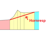
My "problem" your variation is with this section illustrated below. As the bottom of the TH and the first internal panel behind the speaker baffle are parallel to each other, the sections S1-S2, and S2-S3 must have the same expansion, and that expansion must match the expansion for segments S4-S5 and S3-S4 as well in the Hornresp model. This is why I think what you've built really can't be accurately described with a Hornresp model. It can come close, but there will always be an error because S3-S4 can't be described correctly in the model - Hornresp will need an extra segment between S3 and S4 to do so, because in your build the expansion changes between these two points.
It's possible that if you compare the volume of the built horn with the volume predicted by Hornresp, this error might show up. If the net internal volume of your build is not 100%~105% of what's predicted by Hornresp, then the model is probably off. If the net internal volume of your build is below that predicted by Hornresp, then the model is definitely off.
Note also that the "taps" used to calculate the CSA @ S2 and S4 should be taken orthogonal to the center of the path for a more accurate sim.
Hi Brian! Let me try to explain.My "problem" your variation is with this section illustrated below. As the bottom of the TH and the first internal panel behind the speaker baffle are parallel to each other, the sections S1-S2, and S2-S3 must have the same expansion, and that expansion must match the expansion for segments S4-S5 and S3-S4 as well in the Hornresp model. This is why I think what you've built really can't be accurately described with a Hornresp model. It can come close, but there will always be an error because S3-S4 can't be described correctly in the model - Hornresp will need an extra segment between S3 and S4 to do so, because in your build the expansion changes between these two points.
It's possible that if you compare the volume of the built horn with the volume predicted by Hornresp, this error might show up. If the net internal volume of your build is not 100%~105% of what's predicted by Hornresp, then the model is probably off. If the net internal volume of your build is below that predicted by Hornresp, then the model is definitely off.
that's that net volume included throat chamber volume (Atc, Vtc) from my Lonely.TH15_Pro.
I estimated the throat chamber to be 3.5 liters. That should be about right for a 15".
Since I cannot show Atc + Vtc in the drawing, here is the net volume without Atc, Vtc
I need to achieve approximately this net volume in the blueprint so that my simulation in Hornresp is correct, right?
Then let’s see if my blueprint is the result of a stroke of luck?! ;-)
Here is the calculation of the total net volume of the box.
Now the fact is that the corners, I call them "dead corners", are normally NOT part of a simulation. However, they are created automatically when you bend or fold a horn. That is why I have subtracted these "dead corners" from the net volume in the following drawing. With the following result.
As you can see, the actual or real net volume of my Lonely.TH15_Pro = 215.51 liters.
Now we do the following calculation.....
Lonely.TH15_Pro Comparison of simulation and real drawing
net volume without Atc, Vtc = 210,31 liters
Calculation of net volume without „dead corners“ = 215,51 liters
Deviation real drawing to Hornresp simulation =
215,51 – 210,31 = +5,2 liters
+5,2 liters corresponds to an increase in net volume by = 102,47%
....and now you come, Brian ;-)
Note also that the "taps" used to calculate the CSA @ S2 and S4 should be taken orthogonal to the center of the path for a more accurate sim.
With such a flat opening angle, which I normally use for my tapped horns, the effects of how I define S2 and S4 are really negligible!
Best regards, Viktor
really negligible
Hello Viktor,
Complementing what Brain mention but using image.
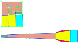
If you compare the Folded box with Unfolded one vs the parameter you input on hornrep, you will see that the volume represented the the area colored with red in attached image is not considered by hornresp model, so your real box is bigger and has slightly different shape close to the driver position then you simulate, when this happen you loose accuracy. How much this will affect the response will depend by the size involved. Bigger the difference between S3 and S4 bigger is the error.
If it's negligible, measurement vs simulation can help on that, if it's a good sing to encourage other to build this MTH modified design.
ROAR is also other design people build that has some accuracy issue.
Regards,
Attachments
Yes, that's a better explanation of the issue I was trying to point out.
Use of the Advanced Centerline to map out the path down the horn does seem to give a good idea of the net volume of the build, so there's no need to arbitrarily remove "dead corners" from the calculation of the net volume. I started some time ago to include volume comparisons in my spreadsheets (net volume calculated from gross volume minus volume occupied by the panels making up the box, compared to calculated volume for the build using basic trigonometry), and I found that the results were pretty close.
Note also that Hornresp does not account for the volume occupied by the driver in the horn, but that's another matter for discussion 🙂.
I had a bit of free time this morning, so I updated my MTH script to calculate the volume difference between a folded MTH build and the corresponding Hornresp model. Works out that the build is about 5%~6% larger than the corresponding model, depending on the expansion angle. I also managed to find a minor bug in the path calculations for the sheet which I sorted out.
Lesson here is that if the actual net volume of your build (total box volume - volume taken up by the panels) is less than 105% of the Hornresp model, then your model is likely incorrect.

Lesson here is that if the actual net volume of your build (total box volume - volume taken up by the panels) is less than 105% of the Hornresp model, then your model is likely incorrect.
Hallo LORDSANSUI and Brian Steele! Ok, I'll give it a second try.If you compare the Folded box with Unfolded one vs the parameter you input on hornrep, you will see that the volume represented the the area colored with red in attached image is not considered by hornresp model, so your real box is bigger and has slightly different shape close to the driver position then you simulate, when this happen you loose accuracy. How much this will affect the response will depend by the size involved. Bigger the difference between S3 and S4 bigger is the error.
This unfolded version of the TH15_Pro is not shown correctly.
Or to put it another way, it is a “purely theoretical” unfolded version that has nothing to do with reality.
The version that Hornresp shows is also a purely theoretical representation.
Hornresp calculations are based on fixed formulas and algorithms that do not take the real housing itself into account.
Actually, to construct a tapped horn, you would have to fold the housing at least once so that the two sections where the driver is located are directly on top of each other. Like here.
But Hornresp does not even take that into account!
No matter how well I can simulate, Hornresp simply does not know how the housing is folded in real life and how many times it is folded.
That is why the unfolded housing should not look like yours, LORDSANSUI, but rather like I drew it.
Every horn, if you try to fold it in wood, has 2 parallel walls to begin with. That's why we simulate it parabolically.
Then a horn has a straight side and a slanted side. And that's why the horn, I repeat “in real life”, will never look as unfolded as you have shown it.
I understand what you wanted to show me with your sketch.
For me, the horn simply opens more from section S3 onwards than at the beginning. On the one hand, that is “not forbidden” and on the other hand, it often brings advantages when constructing a real housing in wood.
There is certainly a certain “inaccuracy” in simulation, but this inaccuracy ultimately brings me more advantages than the other way around.
If I wanted, I could add such slanted plates everywhere at every corner. This would straighten the horn's shape and thus bring it closer to the predicted horn or simulation. Like here in another drawing.
Now I could say: “Great, my simulation is predicted very precisely.”
And that would certainly make Brian very happy. ;-)
But I say!
Bringing the horn into its perfect shape is counterproductive for the acoustic behavior of a tapped horn.
The good thing about these dead corners is that they have a positive influence on the resonance behavior in our favor.
While the long waves of the low frequencies are not disturbed and pass through the horn unhindered, the high-frequency music components are disturbed all the more and are broken or weakened as a result.
To put it simply!
If I tried with all my might to bring the horn into its perfect shape, the two disturbing resonances that you actually DON'T want would be just as strong as Hornresp said before.
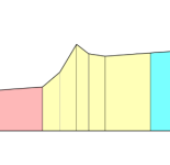
That's why I'm taking a different path in my developments by trying to break up the perfect horn contour and construct my horn as a stepped horn.
I think this image is familiar?
It is precisely these short changes, which deviate from the perfect horn contour, that combat the resonances very well. And the more often you fold your horn, the more effective they are.
long story short.
Tapped horns are purebred subwoofers. A tapped horn has a few disadvantages due to its design. Among other things, it is the two resonances that make a flat separation at the top difficult. That is why I have learned a few tricks over the years to combat these resonances very effectively.
Designing as a stepped horn is one of them.
So that we don't go around in circles and I can leave the “high court” as an “innocent man”.
I have already developed several tapped horn projects, and for each project I built and measured the prototype myself. So I am not a “pure theoretician”. You are invited to look at each of my projects. And also to understand why and for what reasons I do the things I do. So that you don't get the feeling that I'm talking nonsense here.
Here are the development threads.
Lonely.TH12
Lonely.TH12_mkII
Lonely.TH15
Lonely.TH15_Pro
Lonely.TH18
Lonely.TH18_Pro
Lonely.TH8
30Hz_Lonely~HORN
JBELL SS15 Tapped Horn (15mm MPX) + the box 15LB075-UW4
The project is not mine, but I was the one who modified the Jbell SS15 to 15mm wood thickness and thus made it available to the European DIY community.
Incidentally, that was also the “starting signal” for my other PA tapped horn projects.
@Brian Steele
I think your Excel tables are great and I admire your work.
I design my tapped horns completely on my own. For some projects, I even had to build several prototypes to get where I wanted to go.
I design, make mistakes, learn from them and gradually improve my skills. That's why my THs sound exactly as Typ1 described them.
Best regards, Viktor
That is why the unfolded housing should not look like yours, LORDSANSUI, but rather like I drew it
The only difference is if you set centerline horizontal or if you set horn side horizontal. The areas S1,S2,Sn and lenghts, L12, L... are the same. I started my models representing in this way, but some guys prefer the symmetrical representation. For me is the same think and I can work with both.
The question highlighted by Brain and me is related to volumes due to hornresp limitation for total segments.
You can look the site below to check different box models and related hornresp models, all with CAD available for download.
https://freeloudspeakerplan.rf.gd/?i=1
This section of your TH cannot be accurately sim'd using Hornresp. The red line shows what the Hornresp sim is actually representing. The built horn will be noticeable larger than predicted by the sim. Note however that these diagrams just show the various "tap" points along the path and the corresponding cross-sectional area at each tap point along the tap line. They are not a good representation of how the volume varies around the bend and should not be interpreted as such. The representation of the volume in the diagram will only be accurate if the tap line is orthogonal to the path line.

Stepped segments are another beast. But trying to sim the Lonely TH as a stepped horn also has its issues. For the sim to be accurate, the "step" must take place at S3 (for obvious reasons it can't take place at S2 or S4). It can be done as shown in the diagram below, but the problem should be easy to see - the path is no longer continuous, so the path length estimate might be off. I suppose it should be possible to work out the path length around the bend using the advanced centerline method and then using that to calculate the effective value for area S3S, but just thinking about that is hurting my brain, so I'm going to leave that until tomorrow to look at again 🙂.

Stepped segments are another beast. But trying to sim the Lonely TH as a stepped horn also has its issues. For the sim to be accurate, the "step" must take place at S3 (for obvious reasons it can't take place at S2 or S4). It can be done as shown in the diagram below, but the problem should be easy to see - the path is no longer continuous, so the path length estimate might be off. I suppose it should be possible to work out the path length around the bend using the advanced centerline method and then using that to calculate the effective value for area S3S, but just thinking about that is hurting my brain, so I'm going to leave that until tomorrow to look at again 🙂.
Attachments

So, I had some time to have another look at this today, and yes, I think it should be possible to more accurately sim the Lonely TH using this layout, once S3S > 1.3 S3.

Here's a sample sim. Note the step up in CSA @ S3:

I'm trying to figure out how to do this in my BOXPLAN-MTH workbook, and then from there see if I can "reverse-engineer" the Lonely TH, i.e. have it chuck out the corresponding Hornresp sim for the Lonely TH's layout.
Here's a sample sim. Note the step up in CSA @ S3:
I'm trying to figure out how to do this in my BOXPLAN-MTH workbook, and then from there see if I can "reverse-engineer" the Lonely TH, i.e. have it chuck out the corresponding Hornresp sim for the Lonely TH's layout.
Attachments

Hello Brian!
I find it remarkable that you are working so intensively on my simulations, but.........
......somehow I have the feeling that you are opening up construction sites where there is no work. Could that be?
Or to put it another way, you are desperately looking for problems where there are none.
So far, I have managed really well with my way of simulating.
I have never been very wrong in the tuning of any of my tapped horns. All of my projects were exactly as or better than I simulated them. And I simulate all of my THs in this way.
Both the impedance measurement and the frequency response were as I wanted them to be.
And that despite the fact that, in your opinion, I am simulating incorrectly.
Take a look at my development threads, which I linked to my previous post. There are always measurements there too.
Ultimately, I don't want to be the “world's best hornresp-simulator man”,
I'm only interested in what comes out of my tapped horns!
That's what I'm working towards.
And it works!
Kind regards
Hello Viktor,
i get what you mean, i have read trough your TH construction threads and indeed, what HR predicts, match what you have measured and at the end that is what matters right ?
if what HR show deviate a lot from what you have measured , then a go back to the drawing board will be mandatory, but in your case if what the SIMs show matches or exceed the expectations in real life, i call that a WIN WIN situation.
all paths lead to Rome was an ancient saying, so i guess you found another path 🙂
Cheers.
Brian’s overdue for another build. He’s just itching for something to scratch. Maybe this is a sign he’s close to making another ‘POC’ to analyze and share 💚
Hello Max! Thanks for the kind words.
I haven't reinvented the wheel.
I'm just not as rigid about it as Brian.
A horn doesn't have to be perfectly folded to work well. Small deviations from the ideal contour are not bad and even have certain advantages.
That's all I've tried to explain.
Kind regards✌️
I haven't reinvented the wheel.
I'm just not as rigid about it as Brian.
A horn doesn't have to be perfectly folded to work well. Small deviations from the ideal contour are not bad and even have certain advantages.
That's all I've tried to explain.
Kind regards✌️
Last edited:
Primarily it's to satisfy my own curiousity about this MTH variation, hence my work on updating my MTH Boxplan workbook accordingly. The BOXPLAN workbooks make design work a lot easier and allow quick answers to questions like "what if I decreased the width of the box by two inches to fit in my car? " and "what if I used a larger step in the expansion?" etc. The workbook allows the user to change the dimensions of the enclosure and then run the optimization routine to refit the horn to the new dimensions and produce the corresponding Hornresp sim for analysis.Hello Brian!
I find it remarkable that you are working so intensively on my simulations, but.........
......somehow I have the feeling that you are opening up construction sites where there is no work. Could that be?
However, for the workbook to produce accurate results, the sim itself needs to be as accurate as possible, and a sim that shows a change in expansion @S4 where no such change exists in the actual build is just not accurate enough for me (YMMV). Also, if there are any special "benefits" to a stepped change in the expansion as you've suggested, they will show up in an accurate sim of such an arrangement.
- Home
- Loudspeakers
- Subwoofers
- Tapped horn. Lonely TH15 Pro