Hi!all paths lead to Rome was an ancient saying, so i guess you found another path 🙂
I wanted to go into that again. The idea behind my logic is the following........
Simulating a tapped horn with a constant opening angle or a constant expansion in 3 segments is OK, but not particularly effective.
I tried a lot when I first started using hornresp and simulated all the projects I knew.
At some point I started to use the well-known simulation as a basic framework and create my own from it.
And at some point I noticed that a tapped horn with 2 different expansions simulates better.
But the 2nd expansion must not be long.
In the end it should look like an alphorn.
A long tube that slowly opens from the throat of the horn and then opens much more strongly, almost exponentially, just before the mouth of the horn.
I wanted to design something similar for my THs.
Unfortunately, constructing a tapped horn with 2 different expansions is not that easy.
The first time I came into contact with two expansions was when I converted the JBELL SS15 in 15mm wood. The SS15 has two expansions, but the 2nd expansion is very long. That was better than what I've seen so far, but there was still room for improvement.......
The end of the story is that I came up with this trick with the 2nd, short expansion to finally be able to construct my THs the way I wanted.
The result is the projects I listed above.
Everyone is welcome to recreate them and have fun with them.
Kind regards, Viktor
Last edited:

I think (??) the long skinny high pressure section/shape compliments the fundametal resonace when excited by high motorforce drivers ?
If you search in horn response for a location that doesn’t excite the second resonace the driver has to be halfway down the ‘horn’ (instead of 1/3 as in a plain ‘pipe’?
The ‘second expansion’ is occurring in the area that pressure is turning into velocity and complimenting the change with an increase in crossectional area? Then, the ‘Expanding area becomes pressure, not velocity and you continue the ‘horn loading’?
Attachments

Last edited:
@Booger weldz
I don't really understand what you mean?
Powerful, highly motorized drivers with a high Bl value are always good in a tapped horn.
The membrane is or should be stiff to withstand a lot of pressure.
In addition, the compression ratio can be increased and the horn can be constructed steeper. The high efficiency will thank you!
The position of the driver is also very important. In most tapped horns, the driver is as far forward as possible. This gives you more efficiency. I take a different approach. I position the driver a little further back. Ideally, L12 should be longer than L45, but that is difficult to achieve. By extending the L12, the first resonance can be tamed quite well. The extended L12 area can also be used to add some damping here.
This is usually unnecessary if you split your TH steeply upwards.
But sometimes it can be helpful.
As with my projects: Lonely.TH12 + mkII and the 30Hz_Lonely~Horn.
greetings Viktor
What makes the tapped horn so efficient? The fact that it’s bigger than most boxes or because of the shape.?
Hello!
You should perhaps ask the inventor of the tapped horn, Tom Danley! Or David McBean, the developer of Hornresp.
One invented it and knows about it. The other calculates the simulation and thus the efficiency of the TH, and probably knows about it too.
My 5 cents on this topic:
The tapped horn is not just a large housing, but a long tube. A sound guide that opens in a funnel shape towards the mouth of the horn. Popularly known as a horn.
The best examples of this are when you form a funnel in front of your mouth with your hands and your voice gets louder. Another example is when you put your smartphone in a cup and turn on music. The sound gets louder and also deeper. All of this demonstrates the horn principle, which increases the sound level.
A tapped horn is of course not as efficient as a real horn (frontloaded horn), because it is tuned to a quarter wavelength. Nevertheless, there is a good increase in efficiency.
In addition, there is the excellent sound addition of the two sides of the membrane. And the sound is top-notch, as is typical for a horn.
All in all, it's a great housing concept that you can have a lot of fun with!
Kind regards, Viktor
https://www.facebook.com/share/r/14tRTzFBMr/?mibextid=wwXIfr
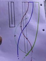
I’m wondering if he’s taking about the full wave length being out of phase with the other side if the driver and the notch created Y that issue or ?
(I just drew a simple folded pipe for ease of visualization)
Thanks for entertaining my silly, ignorant questions 🙏🏻
I’m wondering if he’s taking about the full wave length being out of phase with the other side if the driver and the notch created Y that issue or ?
(I just drew a simple folded pipe for ease of visualization)
Thanks for entertaining my silly, ignorant questions 🙏🏻
Attachments
Last edited:
Tom Danley was talking about the notch in the response on a Synergy mutiple entry horn resulting from the throat reflection of the midrange driver entrance point, some distance forward of the throat, being 180 degrees out of phase with the mouth output. That "notch" limits the useful upper range of the mid driver.I’m wondering if he’s taking about the full wave length being out of phase with the other side if the driver and the notch created Y that issue or ?
That gave him the idea to make a bass horn using both sides of the driver, the rear "tap" delayed by path length 180 degrees from the front "tap", combining in phase, giving up to 6 dB more output over a couple octave range, until the path length difference between the taps becomes out of phase, causing the cancellation dips in the upper range.
So, I think I'm getting somewhere.... 🙂.
There are still a few bugs that need to be sorted out (like the calculation for the horn's volume), but the workbook is generating a sim that seems to be a closer match for this stepped layout.


Along this path of discovery, I came across something else - basically the common "advanced centerline method" will likely produce inaccurate results if the expansion is too large around the bend. Basically, the calculated length around the bend works out to be too long, the end result being that the model ends up with more volume for that section than what's in the actual build. The image below illustrates the issue - if you take the path around the bend and flatten it out, you end up with a path length for the bottom section that is longer than the actual section! The result is a Hornresp sim that's larger than the build, at least for that particular section.

Anyway, I still have a bit of bug checking and cleanup work to do on the workbook, which I'll do, once I get the time 🙂.
There are still a few bugs that need to be sorted out (like the calculation for the horn's volume), but the workbook is generating a sim that seems to be a closer match for this stepped layout.
Along this path of discovery, I came across something else - basically the common "advanced centerline method" will likely produce inaccurate results if the expansion is too large around the bend. Basically, the calculated length around the bend works out to be too long, the end result being that the model ends up with more volume for that section than what's in the actual build. The image below illustrates the issue - if you take the path around the bend and flatten it out, you end up with a path length for the bottom section that is longer than the actual section! The result is a Hornresp sim that's larger than the build, at least for that particular section.
Anyway, I still have a bit of bug checking and cleanup work to do on the workbook, which I'll do, once I get the time 🙂.
Forgot to mention front of the woofer cone i have designed pyramid from massive wood glued and screwed to control the woofer excursion low.After two three different shapes thickness of the pyramid i have the gold balance from output and excursion control.The two subs are loaded with RCFLF15X 400 and the third is loaded with B&C 15NW100.I never use DSP EQ for the subs and mids only crossover filters. I have hard punishment the subs on partys and events indors and outdors for hours with proper filters and limiters and we really enjoy the deep clear bass .Instal the massive wood pyramid for all my tapped horn subs two double 18s two single 18s and four single 12s.I upload photo later from the inside.Guys check this 30hrz performance 15inch tapped horn dimensions 44b-62h-75d crossed at 30hz to 90hz LR 24 from DSP my own design.Just don t copy other plans make your own.I have three of them the bass blow you away.Only the three subs cover two tops 15inch with 2inch driver and two 12inch with 2inch drivers.View attachment 1391440View attachment 1391441
Tom Danley was talking about the notch in the response on a Synergy mutiple entry horn resulting from the throat reflection of the midrange driver entrance point, some distance forward of the throat, being 180 degrees out of phase with the mouth output. That "notch" limits the useful upper range of the mid driver.
That gave him the idea to make a bass horn using both sides of the driver, the rear "tap" delayed by path length 180 degrees from the front "tap", combining in phase, giving up to 6 dB more output over a couple octave range, until the path length difference between the taps becomes out of phase, causing the cancellation dips in the upper range.
Oh, Okay, so the same reflection I sometimes use to avoid the second resonace in a TL (driver tap at 1/3 from the closed end) ?
Can you share your discoveries, pics will be great along the explanation.After two three different shapes thickness of the pyramid i have the gold balance from output and excursion control.
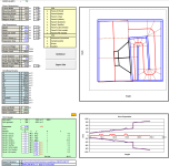
Almost done ...! The optimization routine is now working. Just a bit of cleaning up to do, but the workbook is working ...
Note: I've entered the external dimensions of the Lonely TH15 Pro, set the workbook to assume 15 cm ply, and adjusted the step in expansion and mouth ratio size to produce a result where the mouth height and expansion angle match the drawings for the Lonely TH15 Pro. The corresponding Hornresp sim is similar, but not a really close match to the published Hornresp sim for this TH. So, I'll do some more checks when I can.

Note: I've entered the external dimensions of the Lonely TH15 Pro, set the workbook to assume 15 cm ply, and adjusted the step in expansion and mouth ratio size to produce a result where the mouth height and expansion angle match the drawings for the Lonely TH15 Pro. The corresponding Hornresp sim is similar, but not a really close match to the published Hornresp sim for this TH. So, I'll do some more checks when I can.
I've uploaded the workbook to my site, just in case anyone wants to have a look. It can probably be tweaked a bit further, but I think it's accurate enough now for design purposes.
https://www.diysubwoofers.org/sheets
https://www.diysubwoofers.org/sheets
Uh?I've uploaded the workbook to my site
I only see the same models you had before
Where is the lonely TH15 spreadsheet?
Primarily it's to satisfy my own curiousity about this MTH variation, hence my work on updating my MTH Boxplan workbook accordingly. The BOXPLAN workbooks make design work a lot easier and allow quick answers to questions like "what if I decreased the width of the box by two inches to fit in my car? " and "what if I used a larger step in the expansion?" etc. The workbook allows the user to change the dimensions of the enclosure and then run the optimization routine to refit the horn to the new dimensions and produce the corresponding Hornresp sim for analysis.
Hello Brian!
I see a certain potential for some inaccuracies in your approach.
If someone wants to, for example, make the plan narrower in width in order to be able to adapt it to their desired dimensions, as you say, then that is not always possible without further ado.
And for the following reason! If you make the cross-sections narrower, then the cross-sections grow in height. As a result, the horn line automatically becomes longer when you fold it around the corner. This means that you would have to make the line (in the plan!) shorter to get the same simulation results. But that also means that the L23 area (in the plan!) would have to be shorter, because otherwise the line would effectively be too long.
And this is where the position of the driver comes into play. Look closely at the drawing. The driver is already at the edge with its outer diameter.
So if you wanted to make the width of the housing narrower in the plan, it would actually be impossible to do.
And you only notice that in reality when you unfold your tapped horn as I explained in post #32. And not as you show it in your Excel file.
Otherwise, I think it's very commendable that you're working so intensively on my project and trying to find a certain logic.
However, I think that sometimes you have to break down the logic to reach your goal!
Kind regards, Viktor
Last edited:
I'm afraid my Lonely.TH15 has been assimilated by the MTH-30 or was swallowed by the MTH-30.😱Uh?
I only see the same models you had before
Where is the lonely TH15 spreadsheet?
Hello Brian!
I see a certain potential for some inaccuracies in your approach.
If someone wants to, for example, make the plan narrower in width in order to be able to adapt it to their desired dimensions, as you say, then that is not always possible without further ado.
And for the following reason! If you make the cross-sections narrower, then the cross-sections grow in height.
The purpose of the BOXPLAN workbooks are to use the external box dimensions provided by the user and provide the Hornresp sim for corresponding alignment (e.g. TH) that will fit in the box. It takes any external dimensions for the box you want to use, along with some additional parameters (in this case the size of the step in the last segment of the horn and the amount of the front that's taken up by the mouth) and adjusts the length and volume of the horn accordingly via its "Optimize" feature. For the situation you mentioned, the path length won't change, but the volume of the horn will change, so the response of the design will change a bit. It will be up to the user to decide if that change in response makes a difference.
That doesn't change if the width is decreased. The overall volume of the horn changes however, which will change its response. If that change is significant to the person who wants to reduce the width, well, that's up to them to decide.
- Home
- Loudspeakers
- Subwoofers
- Tapped horn. Lonely TH15 Pro