Bill,
I've looked and measured. I won't have an area large enough to accommodate a subwoofer this large. That goes for inside and outside the shades. It looks like a promising project for a purpose like ours. But I'm going to have to go with a smaller package - even if it doesn't provide as much sound down low.
Thanks for sharing it and for the time and effort you've expended on the project.
The same goes to several others who have been working to produce sims.
Bach On
N.B.: Will publish a 28" Dia x 10 ft Long version (32 ft acoustic length) later this week. It will use an 18" driver. WHG
The diameter is part of the issue. The ceiling is only about 74 inches high. I can't expect the organ tech to crawl on his hands and knees. And the width can't be too large or they can't squeeze by.
It looks like a good concept. We just don't have the space for it.
Bach On
It looks like a good concept. We just don't have the space for it.
Bach On
Blivet ...
... is the military term for the sub-bass part of your mission.
Whatever design you decide to use, I would not put it in the small space you are using for a pipe vestibule. I cant believe there is not a niche somewhere within or adjoining the sanctuary where the sub-bass unit could be flown or otherwise tucked away. Some example's include under the stage or behind a large video screen. At the frequencies of interest, the ear absolutely can not determine where the sound is coming from; so proximity to other pipes is a big non-issue. For notes above, say 64 Hz., proximity becomes increasingly important as frequency rises, so the mid-bass units/pipes need to remain in the vestibule.
WHG
The diameter is part of the issue. The ceiling is only about 74 inches high. I can't expect the organ tech to crawl on his hands and knees. And the width can't be too large or they can't squeeze by.
It looks like a good concept. We just don't have the space for it.
Bach On
... is the military term for the sub-bass part of your mission.
Whatever design you decide to use, I would not put it in the small space you are using for a pipe vestibule. I cant believe there is not a niche somewhere within or adjoining the sanctuary where the sub-bass unit could be flown or otherwise tucked away. Some example's include under the stage or behind a large video screen. At the frequencies of interest, the ear absolutely can not determine where the sound is coming from; so proximity to other pipes is a big non-issue. For notes above, say 64 Hz., proximity becomes increasingly important as frequency rises, so the mid-bass units/pipes need to remain in the vestibule.
WHG
Last edited:
Just a couple of comments and concerns from reading over the last couple of pages...
1. Several months ago in the other thread you mentioned you wanted an extraordinary amount of bandwidth from your subs, IIRC you wanted them to play from tuning to upwards of 300 hz or so. That's going to be very problematic for a lot of these resonant type enclosures.
2. Transmission lines (including tapped horns, which are TLs with clever driver placement) are 1/4 wave devices, not half wave. To learn about TLs, see quarter-wave.com and more specifically the Alignment Tables article. A 32 foot long enclosure is going to tune you an octave too low as TB46's sim clearly shows. (At a glance TB's sim seems reasonable to me, not sure what mass loading Kravchenko is talking about.)
3. WHG's design looks to be bandwidth limited from about 8 hz to about 40 hz. After 40 hz there's approximately 40 db dips between the peaks. That's not to say a very good design couldn't be derived using the same nested sonotube tapped horn concept, but tapped horns are usually limited to about 3 octaves bandwidth max.
4. End loaded straight walled transmission lines like El Pipo are really bad designs if the goal is extended flat(ish) bandwidth. There are 3 ways to extend bandwidth in transmission lines.
a) Move the driver down the line away from the closed end.
b) Introduce a taper to the line, positive or negative taper is fine, anything except straight walls. It doesn't have to be a linear taper, stepped tapers are fine too, this could be done with nested sonotubes if desired.
c) Add stuffing. Since stuffing is always a net loss it should be the last resort and as little as possible should be used, a and b options should be exhausted first so you can use as little stuffing as possible.
Following these simple directives (which are all outlined in MJK's Alignment Tables article IIRC) you can make a very wide bandwidth tl with response stretching from tuning all the way up to as high as the driver itself can play.
4. While a nested sonotube design seems like a simple enough construction concept I'm not sure exactly how you would glue the nesting ribs in place. You could certainly screw them in place but gluing would be tricky. Not a big deal, just something to think about.
5. While the TC driver being recommended is very nice indeed, you really don't need it. You can get similar performance from drivers a fraction of the price although accurately simulating them is problematic. That's why I devised a method to simulate them accurately. Lower q and lower vas lead to smaller enclosures which can be nice if that's what you want. Cheaper drivers usually want larger enclosures.
6. WGH is right about size being a major consideration. The bigger the enclosure the more acoustic gain you can get. The enclosure size determines the amount of acoustic gain available, the shape (and driver location and stuffing) determine the frequency response.
7. I'm also going to second the motion to look for other places to put the sub (and/or possibly the entire sound system). If you want loud and low you need space. Splitting up the subs and the main speakers may be a bit problematic though, if you really do want the subs playing up to 300+ hz. The subs and speakers should ideally be within 1/4 wavelength distance of each other at the crossover frequency, which is pretty close at 300 hz. Maybe you could move the entire system to a bigger and better place. This would have been recommended from the start if it was seen as an option, but this started out as how to make your single existing box better and has gone totally off the rails since then. If it's going to get continually bigger and better you have to start thinking bigger.
Last edited:
Why?
The application has been abandoned by the requestor.
Thus, only certain issues raised here will be addressed by me.
The application has been abandoned by the requestor.
Thus, only certain issues raised here will be addressed by me.
Just a couple of comments and concerns from reading over the last couple of pages...
>snip<
2. Transmission lines (including tapped horns, which are TLs with clever driver placement) are 1/4 wave devices, not half wave. To learn about TLs, see quarter-wave.com and more specifically the Alignment Tables article. A 32 foot long enclosure is going to tune you an octave too low as TB46's sim clearly shows. (At a glance TB's sim seems reasonable to me, not sure what mass loading Kravchenko is talking about.)
I want it low! This characterization is contrary to that of the TH designer, Tom Danley. For me it is a non-issue. Use simulation to adjust the dimensions as noted in the drawing. This is a musical instrument not a general purpose loudspeaker application. For the record I quote Danely's paper here verbatim:
"A common practice used to reduce horn size is to make it only one-quarter of a wavelength long at the low frequency cut-off. This “short cut” has some very interesting effects on a horn’s performance. Of note is that a quarter wavelength resonance will have a velocity minimum at the throat compared to the half wavelength resonance which will have a velocity maximum at the
throat. The net result of this is that, while there will be output from the horn in its low frequency region, the horn will not yield efficient power transfer until the frequency is increased sufficiently to correspond to the horn being one-half wavelength long."
>snip<
4. While a nested Sonotube design seems like a simple enough construction concept I'm not sure exactly how you would glue the nesting ribs in place. You could certainly screw them in place but gluing would be tricky. Not a big deal, just something to think about.
Air leaks in a horn are a "big deal", they kill its performance. A center grove along the strut length for glue injection solves this problem. We inject glue first and then secure with screws (as a clamp substitute).
5. While the TC driver being recommended is very nice indeed, you really don't need it. You can get similar performance from drivers a fraction of the price although accurately simulating them is problematic. That's why I devised a method to simulate them accurately. Lower q and lower vas lead to smaller enclosures which can be nice if that's what you want. Cheaper drivers usually want larger enclosures.
Large volume displacement under tight motor control (Low Qts) is what is needed for this particular application and others similar. Do not put Volkswagen engines in your Lamborghini unless all you want is "all for show and no for go".
>snip<
7. I'm also going to second the motion to look for other places to put the sub (and/or possibly the entire sound system). If you want loud and low you need space. Splitting up the subs and the main speakers may be a bit problematic though, if you really do want the subs playing up to 300+ hz. The subs and speakers should ideally be within 1/4 wavelength distance of each other at the crossover frequency, which is pretty close at 300 hz. Maybe you could move the entire system to a bigger and better place. This would have been recommended from the start if it was seen as an option, but this started out as how to make your single existing box better and has gone totally off the rails since then. If it's going to get continually bigger and better you have to start thinking bigger.
Typical sub-woofers are operated below 100 Hz. not 300 Hz; and in this application only the first two sub-bass octave's. are of particular interest.
A tubular, tapped horn was chosen for exhibiting acoustic characteristics similar to that of a organ pipes it is to work with. My design guidance is to that it is a musical instrument not a loudspeaker of general purpose use, and yhat it should be voiced (tweaked) accordingly.
WHG

The application has been abandoned by the requestor.
I would think it could still be a viable option if it was tuned to 16 hz instead of an octave lower.
I want it low! This characterization is contrary to that of the TH designer, Tom Danley. For me it is a non-issue. Use simulation to adjust the dimensions as noted in the drawing. This is a musical instrument not a general purpose loudspeaker application. For the record I quote Danely's paper here verbatim:
"A common practice used to reduce horn size is to make it only one-quarter of a wavelength long at the low frequency cut-off. This “short cut” has some very interesting effects on a horn’s performance. Of note is that a quarter wavelength resonance will have a velocity minimum at the throat compared to the half wavelength resonance which will have a velocity maximum at the
throat. The net result of this is that, while there will be output from the horn in its low frequency region, the horn will not yield efficient power transfer until the frequency is increased sufficiently to correspond to the horn being one-half wavelength long."
Well... it's not a horn, it's much closer to a transmission line and if you make it a 1/2 wavelength long it's tuned an octave too low. Tune lower than needed and you give up a lot of output due to excursion demands. I can pretty much guarantee that I can beat any 1/2 wave design you can come up with with a 1/4 wave design, that's just the way it goes when you tune too low. In fact, we can totally forget about 1/4 and 1/2 wavelengths and just use a simulator to tune to the lowest frequency of interest which is 16 hz.
Also, a lot of these resonant designs are only good for 3 octaves (your design was only good from 8 - 40 hz), so if you tune too low you might not be able to extend the bandwidth very high. Using a simple tapered tl with an offset driver and a bit of stuffing can get very extended bandwidth though, several octaves.
Large volume displacement under tight motor control (Low Qts) is what is needed for this particular application and others similar. Do not put Volkswagen engines in your Lamborghini unless all you want is "all for show and no for go".
Large volume displacement is necessary, yes, whether you get it with one driver or multiple drivers. Low qts is not necessary unless you need to keep the box size compact. Qts up to around .7 could probably be used effectively, it just requires a bigger box, and that bigger box will have more natural acoustic gain due to it's larger size.
Typical sub-woofers are operated below 100 Hz. not 300 Hz; and in this application only the first two sub-bass octave's. are of particular interest.
Yeah, that's what I would have thought too, but OP wanted a very extended bandwidth for reasons I can't remember.
A tubular, tapped horn was chosen for exhibiting acoustic characteristics similar to that of a organ pipes it is to work with. My design guidance is to that it is a musical instrument not a loudspeaker of general purpose use, and yhat it should be voiced (tweaked) accordingly.
WHG
A tubular end loaded straight walled transmission line might exhibit acoustic characteristics similar to organ pipes but a tapped horn won't. Anyway, it doesn't matter, I believe all the harmonics and everything are built into the signal itself so you need a sub with a flat response, not a wild peaky response full of uncontrolled harmonics. If that was desired the end loaded straight walled transmission line (like El Pipo) would be the best option by far since it would have exactly the same harmonic signature as an organ pipe, the only difference would be that the air flow is provided by a driver.
Last edited:
Yet More Smoke & Mirrors?
The mission you describe is not the one I addressed here. Who said anything about uncontrolled resonances or a wide bandwidth. And the "tuning" for a tapped horn is correct as I designed it to reproduce a strong signal at 16 Hz.
Design tweaking, voicing and conditioning of drive signal have yet to be addressed. These issues have been preempted by a discontinued interest.
If you disagree with Danley, take your issues up with him. In the meantime I will continue to benefit from the use of his methods and those of pipe organ designers as well, as I pursue my acoustic interests mostly outside the limited bounds of this forum. I try to make a contributions here, and have yet again found myself in a place I do not want to be.
WHG
No smoke and mirrors. Sources, sims and links.
Starting at the end, the Danley quote you pulled is about conventional front loaded horns. Tapped horns are NOT conventional front loaded horns. In fact the VERY NEXT PARAGRAPH in that paper describes the fact that tapped horns are quarter wave devices and are designed as such, not half wave.

Here is TB46's sim of your design.

You've got about 112 db at 16 hz and it's already way past xmax with the driver he used to sim it with. That's not much (if any) better than the triangular ported box OP just built with the SI 18 driver. Your design is 1800 liters (internal net), OP's current ported box is a fraction of that size. Your suggested driver is $750 on sale, OP's SI driver is a fraction of that. The whole problem here is that your design is tuned an octave too low.
Also notice that your design is clearly bandwidth limited from about 8 - 40 hz, above that it's just wild uncontrolled resonances.
Wide bandwidth was addressed months ago in the preceding thread. It's a long thread and I can't find a specific source right now from the OP so this will have to do for now. IIRC the reason for the wide bandwidth was because the sub would have to cover the entire rank and ALL the harmonics that the pipes in that rank were going to produce.
"If the 32" "Subbass" register C - G (32 pedal keys) are to be reproduced by the subwoofer, it must cover the 16.346 Hz to 98 Hz frequency range."
"Yes, and quite a lot higher, since higher harmonics of those pipes will also be coming from that box . . . harmonics, "chiff" or wind noise included in the sample, etc."
http://www.diyaudio.com/forums/subwoofers/272833-16-hz-church-organ-16.html#post4293956
I'm sorry you don't want to contribute here anymore but if you want to chat a bit more you will find that I have good reasons for everything I say and I can back it all up with sources and links.
Last edited:
I had been curious where this thread was going to go. Hopefully it does continue. I remember when I was designing a subwoofer for my bass guitar a few years back and it had a B00(15.44hz) string. Was fun while it lasted.🙂
@ whgeiger
Please don't be dissuaded from posting further. I for one, & i expect others, have appreciated your contributions. It's obvious you are very experienced, & skilled in the art etc.
I also loaded tb46's sim 🙂 into HR, & discovered the same things that just a guy did. I tinkered with the design & was able to raise the SPL to 120dB @ 16Hz. But after that it still droops a Lot before peaking again, & is not very smooth after that. I imagine if i/we spent more time on it, it might be possible to improve it further, in some way/s ?
*
To All.
People who have different opinions etc, often contribute in ways they might not always realise, or get thanked for ! Sometimes egos "might" get in the way with "some" people, other times it can be a dogged determination to be proved right. Nothing wrong with being right of course, but being wrong is how we sometimes learn, if we're wise enough to take it on board 😉
Not pointing the finger @ anyone in particular, only trying to keep things flowing 🙂
RAWC Again
There are two lengths marked with asterisks on the drawing plus driver selection to play with. Within the limits of 8 & 16 Hz tunings there should be a performance sweet spot. The problem is finding it and still maintaining a safety margin for the driver. In any event, more output should be obtained from a TH than that of a BR alternative that uses a driver of the same volume displacement. In any case the TH is going to be larger and heavier because it simply has more skin in the game. If the full rank of large organ pipes are to be covered, then I would cover the upper range with a second smaller unit placed in the pipe vestibule. Note that the cost and size of the pipe rank that is to be emulated electro-acoustically is at least two magnitudes larger. If this can be achieved for less than say, $5k USD, that feat would be just short of Divine intervention. BTW the use of DSP for signal conditioning I suspect will be mandatory for this application.
Regards,
WHG
@ whgeiger
Please don't be dissuaded from posting further. I for one, & i expect others, have appreciated your contributions. It's obvious you are very experienced, & skilled in the art etc.
I also loaded tb46's sim 🙂 into HR, & discovered the same things that just a guy did. I tinkered with the design & was able to raise the SPL to 120dB @ 16Hz. But after that it still droops a Lot before peaking again, & is not very smooth after that. I imagine if i/we spent more time on it, it might be possible to improve it further, in some way/s ?
*
To All.
People who have different opinions etc, often contribute in ways they might not always realise, or get thanked for ! Sometimes egos "might" get in the way with "some" people, other times it can be a dogged determination to be proved right. Nothing wrong with being right of course, but being wrong is how we sometimes learn, if we're wise enough to take it on board 😉
Not pointing the finger @ anyone in particular, only trying to keep things flowing 🙂
There are two lengths marked with asterisks on the drawing plus driver selection to play with. Within the limits of 8 & 16 Hz tunings there should be a performance sweet spot. The problem is finding it and still maintaining a safety margin for the driver. In any event, more output should be obtained from a TH than that of a BR alternative that uses a driver of the same volume displacement. In any case the TH is going to be larger and heavier because it simply has more skin in the game. If the full rank of large organ pipes are to be covered, then I would cover the upper range with a second smaller unit placed in the pipe vestibule. Note that the cost and size of the pipe rank that is to be emulated electro-acoustically is at least two magnitudes larger. If this can be achieved for less than say, $5k USD, that feat would be just short of Divine intervention. BTW the use of DSP for signal conditioning I suspect will be mandatory for this application.
Regards,
WHG
Last edited:
Even if I cannot use the designs recently being described here, I feel the discussion is good. Many approaches may work to reproduce the sounds of a pipe organ. WHG's approach for the lowest sounds seems an attempt to produce a speaker similar to the 32 foot pipes that create sounds on an organ below 32 Hertz.
If others feel that other ways are superior, that is their view. Personal tastes in sounds vary. Sims may show many characteristics that are very useful. I'm often in awe of those who can model designs and come up with predictions that are very useful. But personal tastes may - notice I said MAY - trump the science and physics.
I don't think universal agreement is required. But I continue to encourage a collegial approach. That often results in the most - though not always the best - brainstorming.
Keep those cards and letters coming in, folks!
Bach On
Deeper Concept
What I had in mind and yet to explain follows:
The digital wave files used by the organ synthesizer for individual note production would be tailored and sent to the tapped horn for note generation (not reproduction). I expect that with this approach, the whole rank of pipes could be emulated in only two tapped horns, several magnitudes smaller than the rank assemblage. Suspect that driving signal if sent to a typical loudspeaker would sound nothing like an organ pipe, but the horn when driven by such a signal would. Such voicing would require a two step iterative process. 1) Tweaking the horn for this mission, and 2), Tailoring the drive signal file for each note. When I said earlier that my intent was to design the horn as a musical instrument I really meant it. Where it gets real interesting, is when a cord is played in such a system. And as an after though, the imperfections in this system may well yield an acoustical signature of it own that is pleasing to listen to as well as dynamic and visceral.
WHG
Last edited:
What I had in mind and yet to explain follows:
The digital wave files used by the organ synthesizer for individual note production would be tailored and sent to the tapped horn for note generation (not reproduction). I expect that with this approach, the whole rank of pipes could be emulated in only two tapped horns, several magnitudes smaller than the rank assemblage. Suspect that driving signal if sent to a typical loudspeaker would sound nothing like an organ pipe, but the horn when driven by such a signal would. Such voicing would require a two step iterative process. 1) Tweaking the horn for this mission, and 2), Tailoring the drive signal file for each note. When I said earlier that my intent was to design the horn as a musical instrument I really meant it. Where it gets real interesting, is when a cord is played in such a system. And as an after though, the imperfections in this system may well yield an acoustical signature of it own that is pleasing to listen to as well as dynamic and visceral.
WHG
I believe I understand your stated goals. And a new approach MAY need to be tried to meet the goals. And I do understand that the "imperfections" may create a distinctive musical signature that could become valued - at least by some. Perhaps a poor example may be the many "pop" musicians who seem to value the sound of some of the vintage Hammond Organs - replete with rotating Leslies. I've played those things. But I'll never view their sound as valuable. That's a bridge much too far for me.
I'm afraid we'll just have to hold different views on whether such a system is producing or reproducing the organ sounds. 🙂
Bach On
I agree a rotating speaker is not acoustically equivalent to a vibrating air column. I believe a single column of air, driven electro-acoustically can successfully emulate a partial rank of bass organ pipes in a much smaller space and at a much smaller cost. For the upper octaves, I would not even try to do this. Even for the big organs, the variety of bass pipes is limited by size and cost as well and I see loudspeaker/synthesizers being introduced to fill the sub-bass mission. WHG
Post #376
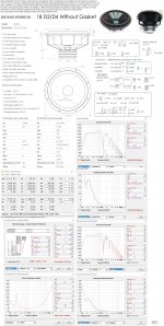
Hi bjorno,
Nice work, you may want to take a look at the measured T/S parameters Mark (mwmkravchenko) posted in Post #306 for the SI HT18.
Regards,
Hi bjorno,
Nice work, you may want to take a look at the measured T/S parameters Mark (mwmkravchenko) posted in Post #306 for the SI HT18.
Regards,
This is an attempt to post a comparison of T/S Parameters for the Stereo Integrity HT-18 Driver. (Bach On has used this driver in one of his bass boxes.) The HT-18 seems to be a budget bass driver with some good bones - at $174 - including shipping.
There is a 2 ohm and a 4 ohm version of this driver. Stereo Integrity only published figures for the 2 ohm version. My recollection is that Mark Kravchenko talked with them via the phone and discovered that the figures they post are "sometimes" figures for drivers they used to sell even when the drivers are now being built by different manufacturers.
Mark has posted his measurements for what appears to be for the 4 ohm version. As you will see, Mark has included many more parameters in his listing (on the left) than Stereo Integrity includes on their website. It should be noted that Just A Guy has disputed some of Marks figures. Mark stands by them. I don't know enough about some of this stuff to take sides. But this is what Mark posted. If JAG posts different figures, perhaps they can be included.
The nomenclature used In some cases is different. I did the best I could to pair up similar items. In some cases I just guessed. 😉This is not intended to be definitive, but only a side-by-side visual comparison of the two sets of figures.
Marks figures are in Black. The Stereo Integrity figures are in Red. I'm sure someone will point out mistakes I've made.
MK's Figures - Stereo Integrity Posted
5. Fres 18 Hz.- 17 Hz.
6. Re 3.9 ohm - 3.5 ohms
7. Dd 387 mm
8. SD 11781.0 mm2 - 11784.1 mm2
9. Qm 4.73 - 5.8
10 Qe 0.562 - 0.41
11 Qt 0.502 - 0.38
12 Df 1.0
13 Cms 0.134 mm/N -
14. Vas 263.04 liter - 411.9 liter
15 Bxl 21.5 N/A - 19.7
16 Mms 592.40 g - 416 g
17.Zres 36.7 ohm
18. Rms 14.077 kg/s
19 Rme 118.570 N*s/m
20 Mpow 10.89 N/1W
21 Mcos
22 Dh
23 fpist Hertz
24 f4pi 282 Hertz
25 f2pi 565 Hertz
26 fmax 887 Hertz
27 Hc mm
28 Hg mm
29 VCd 63.5 mm
30 Xmax 22.0 mm - 22.5 mm
31 Ud 2592 cm3
32 Pe 600 W
33 Gamma 36 m/(s2*A)
34 no 0.251 %
35 Pn 9.3 W
36 SPL 86.3 dB/W - 88.7 dB (1w/1m)
37 SPLmx 111.1 dB
38 USPL 89.4 dB/2.83V
39 EBP 32 Hertz
40 Dvol dm3
The biggest differences I see have to do with various Q figures. Some seem pretty significant. And the Mark's Vas figure is much larger.
Bach On
Quick reference to Vas.
The Mms is higher.
That will lower the Vas.
And lower it is .
BL has two components.
B - magnet flux density or strength of the magnet charge in the magnet itself.
L - length of the wire in the coil.
One of them has changed. Or possibly both of them has changed. You can make the math balance a number of different ways.
To dispute this is actually kind of crazy.
The posted numbers on the website are for a driver that was a prototype made by a totally different manufacturer than the current one.
The driver I tested was bought within two weeks of Ron's (Bach On) purchase. And it is from the same driver run as the one Ron purchased
Measurements are simple.
You make them.
And you post them.
It's not something that is new to me. I have made many hundreds of driver tests in just the past year.
Ironing out the error on the original Vas numbers were due to a scale being inaccurate. That's what I get for carting it all over the world and not calibrating it. That I apologize to you guys for, and an apology to Nick for posting erroneous measurements about his Driver.
With the calibration of the mass used in the measurement we have solid numbers.
I use the same ceramic magnets for Vas testing. A large driver like the HT 18 gets all of them. So to recalculate the mass used all I have to do is measure all the magnets and record the mass. Redo the calculations and bingo.
The electrical measurements are not changed by an inaccurate number punched in on my part for the Vas calculation.
The surface area is slightly different. Not to big of a deal. It will slightly change the efficiency calculation and the Vas calculation. But not by much.
Keep in mind that the math holds up. The error I introduced was an incorrect value for the mass. When the software ran the test the change in Fs was real and valid. With a correction of the mass number used you can do the math again and you get the final numbers I put up as a correction.
The number used for the surface area was a judgement call on my part for half of the surround to half of the surround.
Some of the other numbers posted are actually quite useful if you know what to do with them.
- Status
- Not open for further replies.
- Home
- Loudspeakers
- Subwoofers
- Tapped Horn Cabinet for 16 Hz. organ speaker