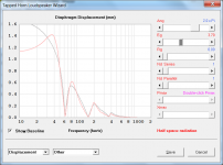
First double up Re (or add Rg equal to Re). Then add power until the circled part of the displacement graph matches up.
Hi just a guy,
How do you match up the displacement curves for a tapped horn? Do you simply find the best overall fit by eye, as shown in the attached example, or is there more to it than that?
It's a pity that the displacement curves can't just be matched at a single frequency (say 4 x fs for all loudspeaker systems, for example). That way, it would be feasible to have a 'Tweak' tool in Hornresp 🙂.
Kind regards,
David
Attachments
I like it. Small, powerful button-sized magnets are cheap at the local crafts supply shop. Thanks.
I stole the idea to!
I found it best to use ferrite magnets. The neodymium ones are simply to difficult to work with.
I can't remember where I first read about the idea. But it's a good one.
Mark,
Thanks for the BBC pamphlet. I can see that my original idea was worse than useless. So I'll have to go back to the drawing board - and back to the home improvement store.
Thanks,
BO
Thanks for the BBC pamphlet. I can see that my original idea was worse than useless. So I'll have to go back to the drawing board - and back to the home improvement store.
Thanks,
BO
Hi Mark,
When I see one mass measurement (Mms) saying (yours, Post #199) 843.5236g, and another (from data-bass) 446.6g, and the manufacturer's 416g I kind of feel that I'll stop designing or simulating until I have T/S parameters that have been measured for the specific driver that I'm simulating for. Which is what should probably be general practice anyway.
Regards,
Hi Bach On,
I lost track of what you are trying to accomplish w/ the door and wall treatment. Maybe you can provide a small sketch and description of the sound insulation part of the project?
Regards,
I lost track of what you are trying to accomplish w/ the door and wall treatment. Maybe you can provide a small sketch and description of the sound insulation part of the project?
Regards,
tb46,
The goal is to reduce some of the sound exiting the rear wall into the nursery. I'm not talking about soundproofing. The construction won't lend itself to that.
We had one layer of sheetrock on the outside wall - with 2x4 studs at 16 inches on center. We put 3.5 inch batts of rockwool insulation in the voids between the 2x4s. Then we put another sheet of sheetrock on the interior wall. Obviously, this only muffles the sound slightly. But remember that both the bass boxes are located right at that wall. And the ports for both open into the space right in front of the door.
The door was put into that wall to allow access to the speakers. It is a simple hollow core wood door in a pine frame. I intend to use weather stripping around the door jam. But I wanted to also do some similar "sound treatment" on the door itself.
Again, I'm aware that none of this is going to stop sound from migrating into the nursery. But I want to do make an effort to reduce it slightly - if for no other reason than to be able to say I tried. I'm not indifferent to the effect of sound going into the nursery, but I also don't have adequate money in the budget to do a lot to address the issue
Mark and Ben were attempting to advise me on how to maximize the effectiveness of my efforts.
Bach On
P.S. I got all the speakers in the chamber last night. Unfortunately, I'd stupidly forgotten to carry my caulking gun and the PL Adhesive. So I'll be going tonight to attach the top to the triangular box. I have temporary spacer boards inserted so I can apply the adhesive and pull the spacers out to drop the top into place. I figure the adhesive in the joint will need 24-48 hours to set. I'll also connect the last two HC12s and their two PP speakers. Then I can begin to test the entire setup.
In moving one of the HC12s, one of the men who was helping me let the bottom of the box drop too low as we were putting it in place and it struck the top of one of the oboe pipes. The horn broke off the motor. It will require soldering the horn back on. I'm afraid this is a job that will be beyond the abilities of Bubba's Welding Shop. So it will probably need to be sent off to be repaired. Didn't plan on that! 😡
Hi Bach On,
Sorry to hear about the broken off motor, don't underestimate Bubba though, welding, silver soldering, lead soldering it's all not too difficult.
As to insulating the door, it's the gaps around the door leaf that need treatment, so you're on the right path w/ the weather stripping, and obviously a second door hung into the same frame from the chamber side would be helpfull. Generally, gaps pass sound, and usually are not taking into consideration during original construction. Maybe a threshold is already at the bottom, or can be added that the door seals against?
Regards,
P.S.: I have a relatively simple fix for the T-TQWT drawing/design(?) to level the response: increasing S1 to 1400 and decreasing S4 to 400 cm^2 together w/ some fill should work. But that's for the winter. 🙂
Yep on sealing the door. I've bought a couple of tubes of clear silicone caulking to address the gaps between the wood and the sheetrock. But there's only so much I can do to stop the sounds from migrating into that nursery area.
You've probably seen some of my posts regarding the limited volume of sound coming through the shades. I asked some questions over at the organ forum. The responses I'm getting suggest that the opening from our pipe chamber is much smaller in comparison with the pipe/speaker chamber than it should be. And it has been that ways since the organ was installed back in 1928. Some are suggesting two similar sized groups of shades on either side of the original shades - spread out across the Sanctuary wall. These would need to work in tandem with the original set.
I'm guessing that the cost of this could be upwards of $5 thousand dollars - perhaps much more. We obviously don't have the bucks for it now. Too, when you are adding something very visible to everyone in the Sanctuary, the "decorating and beautification police" get involved. And differing tastes and style preferences can quickly create a ticklish situation.
I think it was that great philosopher, the Wicked Witch of the West, who was pondering aloud how to accomplish her goal. Her answer was, "Very delicately!" It will take diplomacy and a quiet, steady campaign of building support for such a change among key leaders and those willing to pay for it.
The point is that increasing the size of the opening(s) from the chamber to the Sanctuary may allow more of those low sounds that are already being produced in there to be heard out in the Sanctuary. Thus, the extra bass speaker may not be required. Plus, my eyeball thinking has yet to spot a real good place where I can fit another relatively large cabinet.
I've raised the issue of the shades with our organ tech. He says let's see how the new install sounds before we get our panties in a wad.
As for that broken pipe, I just don't know if the high heat from soldering right at the base of the horn would damage the reed assembly within the motor. I'm guessing we're looking at less than $200 to send it off and have it done by the experts.
Frankly, we've been lucky. I've mostly been the one working in there. And I've tried to be VERY careful working around the pipes. This was a part of the project where I needed assistance. It was just an accident by someone who didn't realize the risks. If that's the worst problem we experience, I'll be happy. Stuff happens!
BO
Last edited:
Yep, the door is the weakest link. I would swap the hollow core door and jamb for an exterior steel prehung complete with good seals and threshold. That and what you did already should offer noticeable improvement. Then if the wall is not yet taped, I might take the 2nd layer down and find a bunch of scrap vinyl flooring to sandwich between and rehang.
Hi just a guy,
How do you match up the displacement curves for a tapped horn? Do you simply find the best overall fit by eye, as shown in the attached example, or is there more to it than that?
It's a pity that the displacement curves can't just be matched at a single frequency (say 4 x fs for all loudspeaker systems, for example). That way, it would be feasible to have a 'Tweak' tool in Hornresp 🙂.
Kind regards,
David
Decreasing Bl instead of tweaking Re sidesteps this whole issue nicely, the only reason I don't endorse only the Bl method is because I haven't vetted it yet. All my time has been spent defending the tweak instead of refining it so far.
As mentioned the Re tweak also skews sensitivity so any information related to sensitivity in any of the graphs will be wrong. Compensating for sensitivity by adjusting power fixes sensitivity but skews Eg, so no matter what sensitivity or Eg will be wrong with the Re method. The Bl method also nicely sidesteps that issue.
To answer the question though, in the Re method this is how it's done for tapped horn and all other alignments. Match up the circled part of the graph to adjust sensitivity (but thereby making Eg incorrect in the process). (Red is tweaked in all examples shown in this post.)
An externally hosted image should be here but it was not working when we last tested it.
That gives this result.
An externally hosted image should be here but it was not working when we last tested it.
Alternatively, adjusting Bl to 80% of it's published value gives this result, and sensitivity is correct so power does not need compensation and all other generated graphs are also correct.
An externally hosted image should be here but it was not working when we last tested it.
The Bl method has clear advantages but I need to do a few dozen study example sims to find the most correct average percentage of Bl to use for generic tweak purposes so the tweak is as useful as possible for all drivers of this type. (From this example alone it looks like 80% Bl will correlate pretty well with the 2x Re tweak, but this single example is the sum total of my work on the Bl method so far.) Of course you can get more accurate by adjusting Bl more precisely by curve fitting to a known good extremely accurate measurement, but if there's no measurements available the generic tweak is always valid and still very good.
It would be a huge honor to have my work included in Hornresp but I would strongly suggest using the Bl tweak instead of the Re tweak. I can have a generic Bl tweak (with plenty of supporting evidence and examples and a more formal and in depth webpage written on the topic) within a few days. For some of this (mainly using images of measurements on the webpage and getting the blessing of the guy that suggested adjusting Bl instead of Re.) I would need to get permissions so it will take some time but having this information accessible might make writing the Help file section easier, and it's necessary to have readily available documentation and examples so people can see it and vet the method for themselves - you would probably not believe the amount of times I've been accused of tweaking random parameters to find a curve fit that would not be useful for anything like different drivers and/or different enclosures.
As I said it's a huge honor that you would even consider this so give me a bit of time to make it worthy and I'll email you when I get close.
Last edited:
Hi Mark,
When I see one mass measurement (Mms) saying (yours, Post #199) 843.5236g, and another (from data-bass) 446.6g, and the manufacturer's 416g I kind of feel that I'll stop designing or simulating until I have T/S parameters that have been measured for the specific driver that I'm simulating for. Which is what should probably be general practice anyway.
Regards,
The very reason why I did the measurement in the first place.
The driver was bought very close to the same time Ron bought his.
Less than two months ago. So it is probably the same driver production run.
The BL is higher.
One way to get this is to increase the amount of wire in the gap. That means more mass.
The greater mass and the lower efficiency add up. I could do a reverse engineering calculation to determine exactly how much more wire and the number of turns required to push up the BL.
There is another way to raise the BL product. It's two parts right. B is flux density. L is length of wire. But to push up flux density you would see an increase in the efficiency and a higher Fs. A much more damped system when you increase flux density.
But to do a decent simulation with driver parameters moving around this much from stated numbers, we really need measurements on the driver that is being used.
Last edited:
Mark,
Thanks for the BBC pamphlet. I can see that my original idea was worse than useless. So I'll have to go back to the drawing board - and back to the home improvement store.
Thanks,
BO
CGC has a similar pamphlet as does Owen's Corning.
Hard to argue with a paper. It listens, but does not talk back.
Usually.....
I'll email you when I get close.
Excellent, many thanks just a guy.
Kind regards,
David
I broke a finger Sat. So can't play upgraded organ for 6 to 8 weeks.
Murphy was an optimist.
Bach On
Murphy was an optimist.
Bach On
What four ewe broke your finger?
Yard work. Tripped over trash can lid and banged back of hand on concrete. Hand swelled up like baseball glove.
Left hand pinky broke at base where it enters back of palm. Going to see surgeon Friday. May need pins because of the way it broke (at angle). Otherwise it will heal crooked. Got it in a splint now that looks like an AK47.
Pain Hertz. 😡
BO
It hurts just thinking about it.
I broke a bone on my right hand just inside the palm ahead of the pinky. There was nuttin to be done except allow it to heal.
Couldn't shake hands for quite a while.
A hand shake would drop me to my knees.
I broke a bone on my right hand just inside the palm ahead of the pinky. There was nuttin to be done except allow it to heal.
Couldn't shake hands for quite a while.
A hand shake would drop me to my knees.
Sorry to hear of your injury.
There are a number of piano concertos for one hand, esp the jazzy one by Ravel. Leon Fleischer toured with one hand.
No organ music for 3 hands and 4 feet?
Ben
There are a number of piano concertos for one hand, esp the jazzy one by Ravel. Leon Fleischer toured with one hand.
No organ music for 3 hands and 4 feet?
Ben
- Status
- Not open for further replies.
- Home
- Loudspeakers
- Subwoofers
- Tapped Horn Cabinet for 16 Hz. organ speaker