SRM12X cross-over continued
I did find some interesting reading on the cross-overs and the autoformer.
I will share an article on the modification of a standard cross-over, where the issue of the autoformer plays a big role.
Also, found a summary from the Tannoy R&D on improving of the cross-overs, which can be found on the newer mid 80's and younger cabinets;
1 - Printed Circuit Boards are detrimental to sound quality.
2 - Star earthing is of paramount importance.
3 - Components must be held down securely to prevent microphonics.
4 - Wiping contacts and switches downgrade sound quality significantly.
5 - Gold plating of electrical contacts is beneficial to sound quality.
6 - Connecting cables can have audible effects.
Some of these issues are also addressed in the cross-over upgrade article;
1 - Use wiring instead of copper traces on PCB, which degrade in time.
2 - As stated, do NOT use long "-" or earth copper trace (or even wire) but, just as in normal live earthing, lead all wires to 1 central point. This way you will never have the possibiity of current delta's / ground loops / HF oscilation on the "-" wire in the cross-over.
3 - Glue them or tie wrap, I found that the "hot glue pistols" work very nice.
4 - The other issue with the autoformer and the option to be able to select HF level and HF roll-off, they use switches.
BIG question, WHY not measure and listen and find your optimum for level and roll-off and then replace the switches with fixed wiring and the appropriate components for the filter HF level and roll-off. I can't see a point in having selector switches when the loudspeaker is used in a fixed setting. If you want to move it from one location to another and another and another, OK. I WILL NOT, will you??
5 - Replace the switches, IF NEEDED, for plated contacts and pins, as seen in newer models.
6 - Use quality cabling, ALSO in the filter it-self.
Also, the K3149 is used in both the LRM12, SRM12X and Edinburgh cabinets. Do they all share the same cross-over? The Edinburgh is also a serious 200 liter cabinet, which was also stated by some of the DIY'ers here in the forum and found in Bass Box Pro to get a serious low-end.
I'm guessing there was an intended design reason for NOT making a big box. Because the SRM12X was intended for Studio Monitoring use (mid field and main monitor, with the LRM12 as near field), the large 200 l cabinet for the K3149 was not needed, because they where soffit mounted, as per intention by the Tannoy R&D. That would bring a 6dB low end increase, which will make the K3149 in the "little" cabinet sound like a big one. NOT soffit mounting them, will result in the "famous" weak low end. 😉
My current plan is to build one test-SRM12X and use the original cross-over, I have to measure and listen which HF level and roll-off suits me best. I will check the cross-over on corroded copper traces and soldering points prior to installing.
Then I could build a new filter, with the findings of the modification article and leave out both selection switches including the autoformer and use the appropriate components to replace it, using fixed wires. Would make a MUCH simpler 2-way filter 😀
2 filters with top notch components will cost around 200 euro's, as stated in the article. That's not to bad.
Bombshell: On the autoformer, I found some companies that still produce them, so I maybe I could have 2 custom made (or even start an autoformer supplier company... 😎
Your thoughts / ideas ?
kind regards,
Last edited:
Cross-over modification article
Just by accident, or by deep mining the web 🙄
I found this article on some-one who seems to know what he's doing here. Gave me more insight in filters, issues with them and solutions / alternatives.
It happened he also used the Tannoy R&D findings as mentioned in my previous post.
The article is very informative and holds foto's to show the solutions.
Much credits to John Kenneth Wynn here.
It's this solution to get a good cross-over for my K3149's, I want to use.
I know, the SRM12X will not be "standard" any more, but it wasn't in the first place. I will build a replica, since there are no original cabinets. Just like restoring an old car, what's not there or unrepairable needs to be replaced.
The cross-over however, could bring so much more to the table, that this NOT being the original filter is not an issue by me, for this project.
Autoformer;
Did send a message to a guy who specialises in autoformers and one of specials. Let's see if we can come up with a solution to build exact replica filters.
kind regards.
Attachments
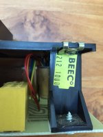
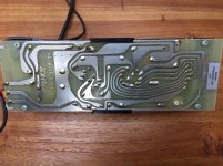
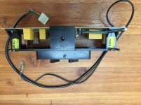
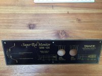
SRM12X Cross-over WITH autoformer
So far, I kind off settled with the idea that I was never going to get my second cross-over for the SRM12X.
Making one from scratch would give me some challenges;
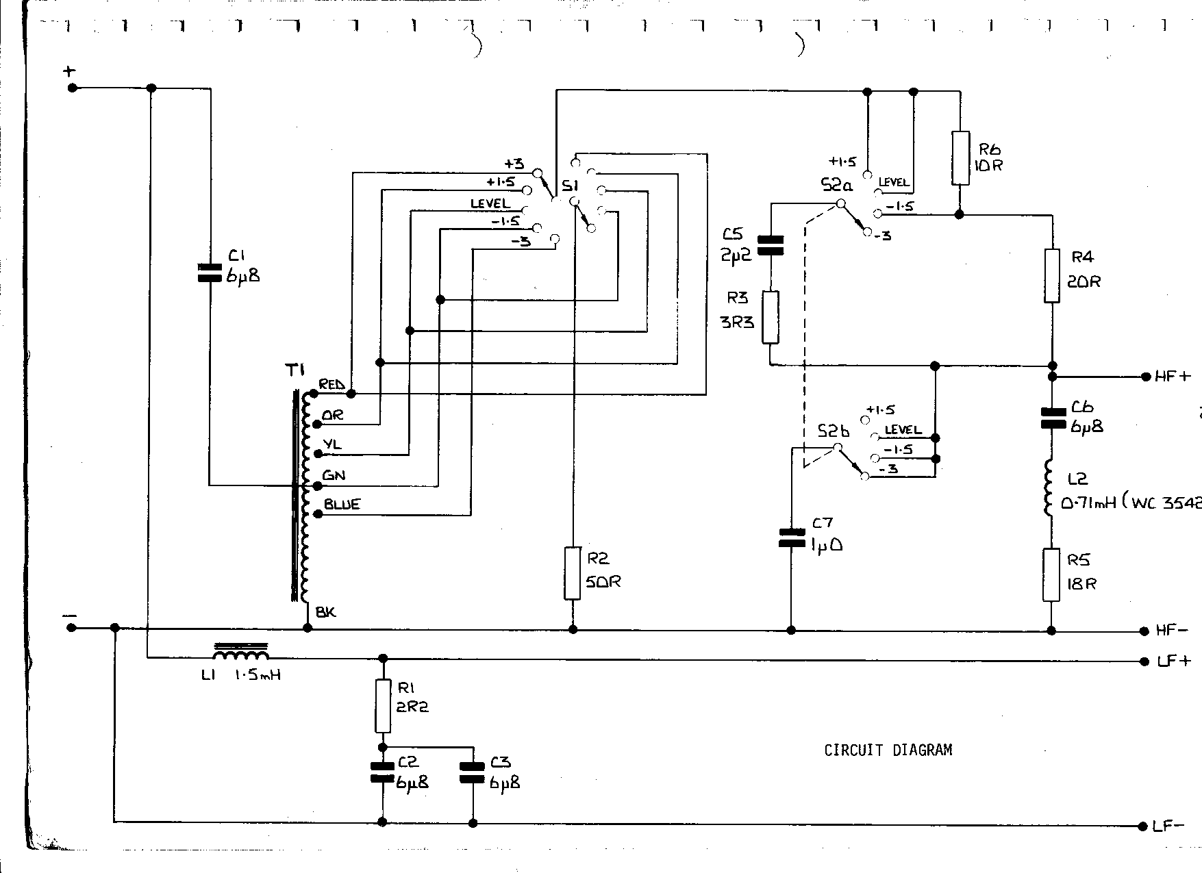
- I need the filter schema: Got that
- I need the components: Not a real issue, except for the so called autoformer
- I need to build the same physical frame, or at least the part that sits behind the filter front: With a bit of creative engineering can be done.
Having said that, I think the real issue will be, it will NEVER be the same as the one filter I currently own. Which means I need to build 2 and use my current one as a museum peace 😉
On the autoformer, although at first never thought I could get hold of one, just happened to find a guy in the USA who could supply me one (at least that's what I was asking for). Luckily he pointed me to the fact that building one is NOT a wise road to travel. OF-COURSE I need two from the same materials, build the same way. That's the only way I would get 2 almost the same (give or take a most likely ignorable tolerance).
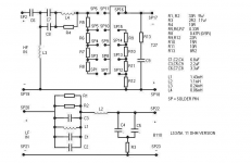
Added are some pictures of the filter and it's front plate, need some cleaning here but that's ok.
Although recreating the old filter, I WILL change a few bit's. At least do the following;
- Do some more reading on filters (not my prime expertise but I understand electronics to an acceptable degree). We are talking the 60's and 70's here when I tried (well not really) to get a degrade in Electronics, but at that time the "Music, girls and having fun" part of my live successfully killed the ambition to get the degree..... 😱 / 😀 "Now pay some attention boy, You'd have, I said, You'd HAVE to get that knowledge into your little head you know..... (Yeah LOVE Foghorn Leghorn). 😀
- Apply some improvements on the physical side of the filter, like wiring instead of copper traces, star-earthing, improved components, NO switches but gold plated connectors , etc.)
- Change the wiring to the drivers and the connection panel
- Make it bi-wireable on the connection panel.
To be continued,
kind regards
So far, I kind off settled with the idea that I was never going to get my second cross-over for the SRM12X.
Making one from scratch would give me some challenges;
- I need the filter schema: Got that
- I need the components: Not a real issue, except for the so called autoformer
- I need to build the same physical frame, or at least the part that sits behind the filter front: With a bit of creative engineering can be done.
Having said that, I think the real issue will be, it will NEVER be the same as the one filter I currently own. Which means I need to build 2 and use my current one as a museum peace 😉
On the autoformer, although at first never thought I could get hold of one, just happened to find a guy in the USA who could supply me one (at least that's what I was asking for). Luckily he pointed me to the fact that building one is NOT a wise road to travel. OF-COURSE I need two from the same materials, build the same way. That's the only way I would get 2 almost the same (give or take a most likely ignorable tolerance).
Added are some pictures of the filter and it's front plate, need some cleaning here but that's ok.
Although recreating the old filter, I WILL change a few bit's. At least do the following;
- Do some more reading on filters (not my prime expertise but I understand electronics to an acceptable degree). We are talking the 60's and 70's here when I tried (well not really) to get a degrade in Electronics, but at that time the "Music, girls and having fun" part of my live successfully killed the ambition to get the degree..... 😱 / 😀 "Now pay some attention boy, You'd have, I said, You'd HAVE to get that knowledge into your little head you know..... (Yeah LOVE Foghorn Leghorn). 😀
- Apply some improvements on the physical side of the filter, like wiring instead of copper traces, star-earthing, improved components, NO switches but gold plated connectors , etc.)
- Change the wiring to the drivers and the connection panel
- Make it bi-wireable on the connection panel.
To be continued,
kind regards
Attachments
-
 SRM12X Crossover-hilberink.gif30.8 KB · Views: 1,052
 -
 SRM12X filter autofomer 8212 1000.jpg396 KB · Views: 398
 -
 SRM12X filter backside.jpg849.4 KB · Views: 341
 -
 SRM12X side of filter.jpg816.4 KB · Views: 340
 -
 SRM12X filter front with switches.jpg810.2 KB · Views: 362
 -
 SRM12X filter cabinet front plate.jpg769.9 KB · Views: 277
Why? No sonic improvement from it.- Make it bi-wireable on the connection panel.
wae said:<<<SNIP>>> On the autoformer, although at first never thought I could get hold of one, just happened to find a guy in the USA who could supply me one (at least that's what I was asking for). Luckily he pointed me to the fact that building one is NOT a wise road to travel. OF-COURSE I need two from the same materials, build the same way. That's the only way I would get 2 almost the same (give or take a most likely ignorable tolerance). <<<SNIP>>>
Why do you state that procurring ( autoformers ) is not a wise road to follow?
There are some who swear by good autoformers for their ability to attenuate signal > without modifying the inherent dynamics of a compression driver ( be that good or bad is a different question ).
🙂
Why do you state that procurring ( autoformers ) is not a wise road to follow?
There are some who swear by good autoformers for their ability to attenuate signal > without modifying the inherent dynamics of a compression driver ( be that good or bad is a different question ).
🙂
Hi Earl,
It is not a wise road to follow related to the issue I currently have. I only own ONE (1) original crossover an requested for one autoformer to be newly made. That way I will end up a most likely two different crossovers for the SRM12x's. THAT is "not a wise road to follow", I was referring to.
Since I have to build one new crossover entirely, I'd better make 2 new crossovers. So order 2 newly made autoformers. Also I understood that this company uses nickel as the core over metal, which is supposed to improve the sound / audibility or whatever it may improve.
Which brings me to the following. I have a slight (currently not really funded) averse in to much components in the signal path. The autoformer, which is an improvement over the transformer, still remains a (multi tap) coil which influences the audio signal (by nature of a coil). I wanted to rebuild the original SRM12x (as I do not have the original cabinets) so IF their would be room for improvement, it is likely to at least investigate pros and cons. I've read various articles that, leaving out the autoformer completely, which changes the whole setup of the crossover, was a major improvement. Yet again, like you say, others like it, but maybe more as a solution to be able to change signal levels in the filter. Not so much sound.
Last point I would like to bring up, WHY on earth should we put this device in the signal path with a rotary switch added to it. This is likely to deteriorate in quality and make the loudspeaker sound worse over time. The reason to be able to select energy level and roll off is fine by itself, but I would guess we only do that once and leave it like that. SO, replacing it by a fixed solution, or at least remove te rotary switch, as was done in the newer (West Minster and the likes) models and use a semi fixed selection construction instead.
I'm in the process of making my own selection / patch bay for the autoformer.
Keep you informed.
kind regards.
Why? No sonic improvement from it.
To have the option of using 2 separate amps (class A maybe) which do not, at least the more affordable ones, have a lot of power.
Nothing very specific here.
kind regards.
Hi Earl,
<<<SNIP>>> I only own ONE (1) original crossover an requested for one autoformer to be newly made.
That way I will end up a most likely two different ( SOUNDING added by EK) crossovers for the SRM12x's. THAT is "not a wise road to follow", I was referring to.
<<<SNIP>>>
The autoformer, which is an improvement over the transformer, still remains a (multi tap) coil which influences the audio signal (by nature of a coil).
<<<SNIP>>>
Yet again, like you say, others like it, but maybe more as a solution to be able to change signal levels in the filter. Not so much sound.
<<<SNIP>>>
I'm in the process of making my own selection / patch bay for the autoformer.
Keep you informed.
kind regards.
Thanks for your explanation. Your earlier statement makes sense to me now.
I haven't critically auditioned that particular Tannoy autoformer ( as a part ) > so can't really comment much on it ( though ) ;
- I was prepared to mod my cousins HPD315's some time ago ( I had lot of nice sounding caps that I assumed would be an improvement ).
- Well, I listened to his system first and then decided against it ( somewhat along the lines of "If it isn't broken why fix it? as my thought process ).
HERE's a thread to from another Tannoy user, who changed out his crossovers ( & was quite satisfied with the results ).
🙂
To have the option of using 2 separate amps (class A maybe) which do not, at least the more affordable ones, have a lot of power.
Nothing very specific here.
kind regards.
Yeah, don't bother.
There is no point in using two amps unless you go properly active with a line level crossover before the amps.
As a little anecdote somebody told me once that his LittleReds sounded a LOT better when bi-wired. You know the whole veil lifting, night-and-day, wife heard it from the kitchen spiel.
I have a pair of LRMs and they do have two pairs of posts but that is in preparation for active use, The second set of posts is internally not connected to anything at all. LRMs came with a set of internal cables to bypass the crossover completely which is when the extra posts come into play.
So you can spend even more money on multiple amps that will not improve SQ or apply any more power to the speaker than one of them single amped.To have the option of using 2 separate amps (class A maybe) which do not, at least the more affordable ones, have a lot of power.
So you can spend even more money on multiple amps that will not improve SQ or apply any more power to the speaker than one of them single amped.
No, not really . I was thinking ahead. Just got a message that 2 autoformers will set me back $400 !! JEEZZ, don't know if I'm still in for autoformers, just to adjust HF level. No that's a pretty hefty level matcher, money wise that is, which I only intend to set once and than leave them alone.
If bi-amped, I can easily correct HF level BEFORE the HF crossover part. A pair of second hand amps will go for half that price at the max.
How's that for alternative crossover modification... 😀
The other variation is to completely redesign the filter and leave out both level and HF roll-off, replacing them for a fixed network after some measurements and listening.
QUESTION: What would be wrong with a set of resistors to tame the HF level (like an L-PAD with a series / parallel resistors of good quality)
I don't know yet. Bi-amping does not cost more than $20 for some wire and 2 extra connectors.
Your options are welcome.
kind regards
Yeah, don't bother.
There is no point in using two amps unless you go properly active with a line level crossover before the amps.
Hold your horses..
As a little anecdote somebody told me once that his LittleReds sounded a LOT better when bi-wired. You know the whole veil lifting, night-and-day, wife heard it from the kitchen spiel.
I have a pair of LRMs and they do have two pairs of posts but that is in preparation for active use, The second set of posts is internally not connected to anything at all. LRMs came with a set of internal cables to bypass the crossover completely which is when the extra posts come into play.
So much for hearing and suggestive behaviour. At least A B testing should be used. I would not know WHY it would sound better, unless the somewhat different load (because you present it with a different network) to the amp will make it behave differently. Let's not go there I guess.
kind regards.
FWIW, it's a good plan to multi-wire to only use wiring sufficient for each driver's load, so can definitely 'lift a veil' in some cases plus depending on the values required one can use the HF wiring as a series resistor, a popular tweak among 'FR' driver speakers. Factor in that often that solid core single strand [the ideal] magnet winding wire can be used to feed mids, HF and all these little tweaks add up.
GM
GM
Just got a message that 2 autoformers will set me back $400 !! JEEZZ,
QUESTION: What would be wrong with a set of resistors to tame the HF level (like an L-PAD with a series / parallel resistors of good quality)
Your options are welcome.
kind regards
What about these:
Klipsch loudspeaker corner
To answer the question above an opinion is inevitable: autoformers sound better.
There are comparisons on Youtube for common resistor L-pad, super-expensive resistor L-P and autoformer.
The active system option is excellent. 😎
BiAmp (Bi-Amplification - Not Quite Magic, But Close) - Part 1
Have fun,
M.
I can't think of any reason whatsoever why a cored transformer or autoformer style might be better than a simple air coil in this use. Transformers were traditionally more useful with low impedance microphones and LP cartridges into high impedance amp inputs.
If the Tannoy is being operated in the -1.5dB position, the input and output use the same tap, and the autoformer reduces to a simple coil in effect.
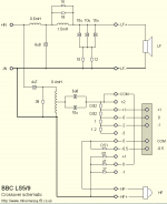
The BBC used an autoformer in early versions of the LS3/5A, but converted it to a simple coil and resistive ladder later. Can't imagine what the agonising here is all about.
If the Tannoy is being operated in the -1.5dB position, the input and output use the same tap, and the autoformer reduces to a simple coil in effect.
The BBC used an autoformer in early versions of the LS3/5A, but converted it to a simple coil and resistive ladder later. Can't imagine what the agonising here is all about.
Attachments
I can't think of any reason whatsoever why a cored transformer or autoformer style might be better than a simple air coil in this use. Transformers were traditionally more useful with low impedance microphones and LP cartridges into high impedance amp inputs.
If the Tannoy is being operated in the -1.5dB position, the input and output use the same tap, and the autoformer reduces to a simple coil in effect.
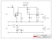
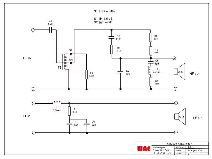
Although not the crossover expert here, I did try to put up a simpler version, leaving out the S1 and S2 switches. I choose the switch setting "-1,5" for Energy and "Level" for HF roll-off.
What I noticed is that the autoformer still takes its place as a 2 tap autoformer. The Green for "straight through" BUT also the Orange tap connected to the resistor. 🙁 Am I wrong here, or is the original schematic wrong. 😕
The BBC used an autoformer in early versions of the LS3/5A, but converted it to a simple coil and resistive ladder later. Can't imagine what the agonising here is all about.
Would be VERY much my preference, assuming the right type and quality resister be used. So how do I get ride of the autoformer??
Help MUCH appreciated.
kind regards.
Attachments
When you want a truly high quality resistor one makes a resistor bank out of very small value resistors same as done for primary resistor motor controllers and if you don't need a lot of resistance, then bi/whatever-wire and size the lead in [solid] wire to get the desired value.
GM
GM
To answer the question above an opinion is inevitable: autoformers sound better.
I want to re-phrase: if you only want -1db attenuation better do an L-pad. If like me, you need -9db, then an autofomer is clearly better.
If the correct attenuation is not clear, i would use a power potentiometer as L-pad and then read the optimal value to swap it for a discrete L-pad. 😉
Have fun.
M.
I'm not in the exotic resistors fanclub. Resistors are resistors IMO, as long as you keep them adequate and hence cool, which avoids temperature dependence.
Autoformers do have the advantage of 100% efficiency. A quality less critical in these days of very powerful amplification.
Now back onto the main topic. Losing the hugely expensive autoformer.
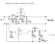
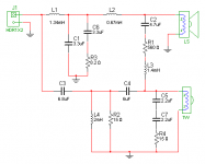
This looks like a good halfway house:
You don't nowadays often see a resistor in parallel with a shunt coil, but in fact it works as an attenuator. Think of it as adding a little resistive power loss to the coil. The Heybrook HB2 was the last example I saw, and I include the (slightly inaccurate, because the shunt coil on the tweeter must be nearer 0.2mH IMO) schematic along with the Rogers LS5-9 autoformer as edifying. The Rogers monitor has fine adjustment because it needs to perform accurately in the broadcasting studio.
Wading through an earlier pdf, I have extracted the pertinent parts. 2.9mH seems a huge value here. It reduces the filter to near first order IMO. I would sim this one to see what it does electrically.
Autoformers do have the advantage of 100% efficiency. A quality less critical in these days of very powerful amplification.
Now back onto the main topic. Losing the hugely expensive autoformer.
This looks like a good halfway house:
You don't nowadays often see a resistor in parallel with a shunt coil, but in fact it works as an attenuator. Think of it as adding a little resistive power loss to the coil. The Heybrook HB2 was the last example I saw, and I include the (slightly inaccurate, because the shunt coil on the tweeter must be nearer 0.2mH IMO) schematic along with the Rogers LS5-9 autoformer as edifying. The Rogers monitor has fine adjustment because it needs to perform accurately in the broadcasting studio.
Wading through an earlier pdf, I have extracted the pertinent parts. 2.9mH seems a huge value here. It reduces the filter to near first order IMO. I would sim this one to see what it does electrically.
Attachments

- Home
- Loudspeakers
- Multi-Way
- Tannoy Super Red Monitor Project