Just replaced one 100VA toroid with a 500VA in my speakers. Thankfully I can turn my preamp to full output and nothing bad happens. The woofers go mental, of course, but no bad noises occur, no protection kicks in, phew!
Simon
Simon
Thanks Paolo.
Hi Simon,
To make best use of the new transformers you would likely need to adjust all other passive components, but I'm sure you already hear more cleanly reproduced lower frequencies due to lower resistance and reduced transformer losses.
Cheers ........ Graham.
Hi Simon,
To make best use of the new transformers you would likely need to adjust all other passive components, but I'm sure you already hear more cleanly reproduced lower frequencies due to lower resistance and reduced transformer losses.
Cheers ........ Graham.
Hi Graham,
I'd not know how to adjust them! I have finished the 2nd speaker now and given it a good blast with a favourite Linn compilation.
The difference isn't huge but it is indeed cleaner - the attack of bass notes is harder and basslines seem to be tracked with a little more definition (less woolly).
Simon
Hi Simon,
The conditions you now describe are ones where you are likely to hear bass notes and definition which were previously inaudible due to 'muddying'.
So now you don't have typical driver enclosure coloured bass, and you are beginning to move beyond what most people would consider impossible via OB working.
Cheers ........ Graham.
Perhaps so. I have in a way downgraded my CD player so my main reference point is not as clear as it normally is. This is why I hesitated to do the tx upgrade. I still need to adjust the crossover filter a little, as 1st order and no zobel or anything still isn't well behaved enough - even with 8mH. 2nd order was a big mistake so I'm now trying the cap in series with a resistor. Sorry, this is off-topic now.
The T-bass part is doing its job 😀
The T-bass part is doing its job 😀
UnixMan said:
I guess what Graham is trying to say is that a loudspeaker is NOT exactly the same thing as some (constant, "fixed" as well as linear) impedance. Specially if you consider the "first cycle" or otherwise non-repetitive transient behavior.
As someone else already pointed out, a simulation is only as good as the model(s) used to perform it.
Unless you have a really realistic model of a loudspeaker which takes into account all the non-linearities, transient effects, etc, SPICE is useless in this context. Unfortunately, AFAIK such a realistic model does not exist.
Hi,
Regarding paragraph 1 I never said it was *. Regarding "first cycle
distortion" this is not an accepted concept for transient analysis.
A sine wave that starts at zero at some arbitrary point is a form
of transient signal, but there many others, take your choice.
Regarding paragraph 2 this is of course true. However the model
only needs to be good enough to provide the approximation you
are after, That its not "true" does not negate what it tells you.
Regarding paragraph 3 I have to disagree.
The small signal behaviour of bass units can be extremely
realistically modelled to tell you nearly everything you need
to know. It is after all a fairly simple electromagnetic system.
AFAIK all loudspeaker system simulators are based on SPICE.
Regarding large signal behaviour of bass drivers see :
http://klippel.de/pubs/Klippel papers/Loudspeaker Nonlinearities–Causes,Parameters,Symptoms_06.pdf
There are some other interesting papers on the above site.
🙂/sreten.
* Strictly speaking impedance is only valid for sine wave drive.
You could though regard it as instantaneous V/I at any point.
Back to the transformer...
I found a 110V-220V autotransformer with 0.7 Ohm DCR across the 220V winding, is it OK? It's a 1kVA transformer and weighs 6.7kg, quite a big guy. (Looking at the picture, I begin to worry about the iron loss.... )
I don't mean to keep bothering you with such dump question. Maybe it's just my obsession. I don't like to see something hanging around without any funtion -- the unused primary winding.
If it's not adequate, then I tend to have it custom-built....
Graham Maynard said:...
Transformer windings generally need to be 20 to 40V per half at 3 to 6A, also <1 Ohm, preferably circa 0.1 ohm.
Line/mains voltage autotransformers are not going to have low enough resistance to drive LF with low source impedance, and if used are likely to impair LF reproduction.
I found a 110V-220V autotransformer with 0.7 Ohm DCR across the 220V winding, is it OK? It's a 1kVA transformer and weighs 6.7kg, quite a big guy. (Looking at the picture, I begin to worry about the iron loss.... )
I don't mean to keep bothering you with such dump question. Maybe it's just my obsession. I don't like to see something hanging around without any funtion -- the unused primary winding.
If it's not adequate, then I tend to have it custom-built....
Hi CLS,
Yes that transformer will work well with a single 8 ohm LS.
Anything over 1 ohm per winding is not going to work well with a low Q driver - there is a recognisable loss of kick and articulation.
Yes an unused primary winding is a waste of possible winding space, but it is not going to introduce LF loss by just being there, and iron loss is not likely to be a problem at the relatively few volts your amp is outputting.
As long as the full winding inductance exceeds say 150mH you should not notice loss of low bass drive.
I would not go out and buy a 110-220V 1kVA transformer for this project; likely almost twice as expensive and with the increased winding loss not as good as 40-0-40V 500W with unused primary.
Hi Sreten,
Will you please go and try the circuit so that you can have some REAL 'ears/hands-on' idea, as opposed to thinking you know, what about what you are writing about !
Hi Unixman,
Thanks. It is as if we are deemed to not understand and need educating.
Cheers ......... Graham.
Perhaps my (temporary!) use of about 2.5DCR's worth of coils following my transformer accounts for why I only heard modest gains in up-sizing there. I will get those changed for <1R shortly and report. I did need to up it to experiment with increased mH and DCR.... more (wanted) roll-off was gained but I also lost quite a bit of definition.
My next OBs will use a more pricey coil to get it down to <0.5R. Is there an overall level of DCR you aim for in your t-bass / crossover systems, Graham?
Another thought I've just had is that my large resistance coils are saving my amp from seeing the full "horror" of mega low impedance at LF.
Simon
Hi Simon,
I would always go for lowest R coils, this then provides greatest range of adjustment via the series resistors.
Yes high R windings protect the amplifier, but sound less good too.
The 'horror' is more due to a lack of series resistance in the capacitor/inductor circuit, and not the transformer/loudspeaker circuit, but even then any decent and genuinely 4 ohm capable amplifier should not be clipping before an OB mounted LF driver overexcurses.
Cheers ....... Graham.
(Sounds like its gone white this morning where you are.)
Thanks Graham, I will let you know what comes of using a more appropriate coil.
We've had the most pathetic covering of wet snow, that has now largely melted away in the rain!
We've had the most pathetic covering of wet snow, that has now largely melted away in the rain!
Graham Maynard said:H
Hi Sreten,
Will you please go and try the circuit so that you can have
some REAL 'ears/hands-on' idea, as opposed to thinking
you know, what about what you are writing about !
Cheers ......... Graham.
Hi,
If you have not noticed this is a forum.
Glass houses and stones comes to mind ....
Whilst not claiming infallibility I do know what I'm
talking about and pretending otherwise is pointless.
😎 /sreten.
sreten said:Hi,
For anyones information: the source impedance driving the speaker.
(Standard circuit but midrange notch filter components omitted.)
As its not voltage drive (low source Z) driver parameters are changed.
🙂/sreten.
Hi Sreten.
That is similar to what I published/reported in another Forum before opening this diyAudio thread.
The effective source impedance in series with driver impedance was one of the main aspects I studied about this circuit.
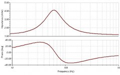
Where there is maximum LF boost from the transformer the circuit impedance is lower, and thus there is maximum transformer generated increase in amplitude.
Around and above driver Fs - where circuit transformer output is falling - there is increased series source impedance, though this arises where the driver impedance is also higher.
Notably this allows low Q drivers to develop a higher Q and thus increased output, though this where the drive is reduced.
HOWEVER. This impedance peak *does not develop until after the first half cycle* of LF input waveform, and thus it also prevents the LF driver from transducing/storing waveform energies which would (and do) otherwise 'muddy' LF reproduction.
Thus the driver receives initial drive amplitude which can be matched to counter coil/cone/air mass resistance to motion with a suddenly starting waveform, and this is why drum reproduction sounds so much more lifelike than I've heard with any other combinations of more conventionally driven drivers/baffles/enclosures. Just clean bass !
The illustrated impedance peak then returns to a low value where the upper bass output amplitude has been much reduced, but not phase shifted !
Notably, the phase variation due to the insertion of this circuit is much less audibly degrading of composite waveforms than are the phase shifts introduced by conventional LP filters (passive or active or EQ) normally used to provide the same overall amplitude response, and low Q drivers have better control of phase variation too.
Reproduction is so much improved that I have tried many ways to achieve the same results without using the transformer, but I have not been able to.
The transformer plus driver work together in a way that a plain NFB SS amplifier plus driver cannot do due to voltage output not matching driver current needs in relation to driver stored energy.
Modified SS NFB arrangements might be possible, or with dual-secondary tube output-transformers, but these solutions do not present a solution like the T-bass which can provide composite LF compensation for OB with most SS amplifiers.
Cheers ......... Graham.
Hi,
Standard theory has difficulties with the phase response of two
systems with identical amplitude responses being any different.
Identical amplitude also means identical transient response.
I'm not tearing up my textbooks just yet ....
🙂/sreten.
Standard theory has difficulties with the phase response of two
systems with identical amplitude responses being any different.
Identical amplitude also means identical transient response.
I'm not tearing up my textbooks just yet ....
🙂/sreten.
sreten said:
As its not voltage drive (low source Z) driver parameters are changed.
that's just about the whole point behind it... 😀
here we are after speaker response eq., aren't we?
BTW: about 4 ohm of drive impedance at "critical" bass frequencies... that reminds me of something! 😉

sreten said:Hi,
Standard theory has difficulties with the phase response of two
systems with identical amplitude responses being any different.
Identical amplitude also means identical transient response.
I'm not tearing up my textbooks just yet ....
🙂/sreten.
What you have written here is ambiguous because you do not qualify the nature of the amplitude response.
Is this a steady sine amplitude response ?
If yes then - "Identical amplitude also means identical transient response." is an incorrect statement.
Hi UnixMan.
You've got it.
The T-bass circuit acts in two ways, with the circuit L and C chosen to match the driver characteristics + mounting requirement.
Using a series resistance will not do the same job due to power/sensitivity loss, whilst the transformer actually increases sensitivity by stepping up voltage where the driver impedance is still high.
If you get a chance, do try the circuit.
It will work with any sized driver, and even with enclosures.
Cheers ......... Graham.
Update
My progress is slow😱
For convenience of modifications, I made a T-bass mockup on a peice of wood and placed it behind the amplifier. (Eventually I dug out my good old Hafler which has been in rest for quite some years... )
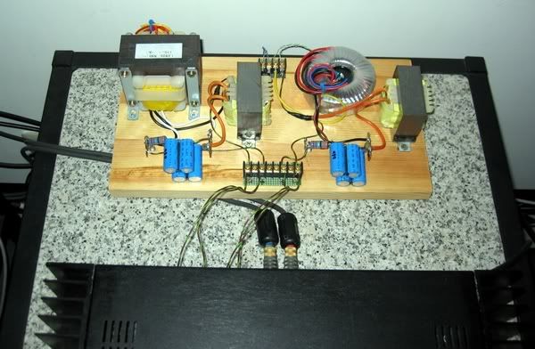
Chokes are EI type, together with transformers were picked up from various "junk" yard (my own and other's old part bins... ). The toroid one on the right is apparently undersize with only 0-6.3-12.6V. (Well, this is a mockup... and my new 400VA toroid ones have just arrived.)
Now the choke is 4.2mH, cap is 700uF with series 3R3. The impedance with driver in free air stays slightly under 2 Ohm in the range of 60~120Hz, with a 'peak' of 10 Ohm at 28Hz. (On baffle, the fs should drop to low 20's, but not measured yet.)
This is the baffle:
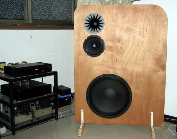
The baffle was originally designed for a single 8" fullranger, which was posted here last year. I added tweeter WG and 18" woofer to make it a 3way.
Low and mid-high are actively xover at about 160Hz (maybe a little higher acoustically, I have not measured it yet)
At first the woofer overwhelmed the midhigh. In addition to the flooding bass, the woofer produced more midrange than the midrange My DIY pre+active xover is not so easy to tune (as turning some nobs), so it took me another night to work on the circuits to tune the gain and xover frequncies...
Last night, after some fast pink noise sweep and fine tunings on the upstream EQ, this new system began to sing beautifully. Not perfect at this stage of course. However the fullrange coherence is very nice. I like the bass a lot 😀
The baffle is 3/4" ply (bad quality) with only minimum supports to stand upright on its own. Now it seems too flimsy to accommondate a heavy 18" woofer (and the air it pumps). The whole baffle was shaken at some bass slams, and squeaked! 🙄 I have to work on it later... Even so, the overall sound is still very pleasing.
Of course more tuning is needed. To be continued....
My progress is slow😱
For convenience of modifications, I made a T-bass mockup on a peice of wood and placed it behind the amplifier. (Eventually I dug out my good old Hafler which has been in rest for quite some years... )
Chokes are EI type, together with transformers were picked up from various "junk" yard (my own and other's old part bins... ). The toroid one on the right is apparently undersize with only 0-6.3-12.6V. (Well, this is a mockup... and my new 400VA toroid ones have just arrived.)
Now the choke is 4.2mH, cap is 700uF with series 3R3. The impedance with driver in free air stays slightly under 2 Ohm in the range of 60~120Hz, with a 'peak' of 10 Ohm at 28Hz. (On baffle, the fs should drop to low 20's, but not measured yet.)
This is the baffle:
The baffle was originally designed for a single 8" fullranger, which was posted here last year. I added tweeter WG and 18" woofer to make it a 3way.
Low and mid-high are actively xover at about 160Hz (maybe a little higher acoustically, I have not measured it yet)
At first the woofer overwhelmed the midhigh. In addition to the flooding bass, the woofer produced more midrange than the midrange
My DIY pre+active xover is not so easy to tune (as turning some nobs), so it took me another night to work on the circuits to tune the gain and xover frequncies...Last night, after some fast pink noise sweep and fine tunings on the upstream EQ, this new system began to sing beautifully. Not perfect at this stage of course. However the fullrange coherence is very nice. I like the bass a lot 😀
The baffle is 3/4" ply (bad quality) with only minimum supports to stand upright on its own. Now it seems too flimsy to accommondate a heavy 18" woofer (and the air it pumps). The whole baffle was shaken at some bass slams, and squeaked! 🙄 I have to work on it later... Even so, the overall sound is still very pleasing.
Of course more tuning is needed. To be continued....
Hi CLS,
Sounds like you are getting there.
Might I suggest having the bottom of the baffle on the floor or on a separate baffle base, but without direct physical contact, say a layer of thick carpet compressed below the lower edge of the baffle to damp it and reduce air path short circuiting.
(You could always try connecting the woofer directly with separately adjusted drive to prove whether a transformer based arrangement is 'worth it'.)
Cheers ......... Graham.
Yes, separating the excited woofer from mid-high should surely be a good thing. My previous setup was a much more stronger bass baffle with a fully 'suspended' midhorn. That assembly worked very good at decoupling vibration. (I have to dump them because of the size is just too big for my living room, sadly.)
Now except for the excellent bass, this new system is actually a downgrade for me. I lost a lot of dynamics and richness in midrange. This 8" wideranger is not up to the job. It's very odd that the system sensitivity is lowest in the midrange. I have to turn down the bass a lot to match it. (What the xxxx!?)
So, this setup is actually an "evaluation board" of T-bass. 😀
Except for the flimsy lousy baffle, a larger and more powerful midrange is a must (say, TD15M), but that'll be a whole new story....
Back to the T-bass, last night I hooked up the new 400VA toroid transformers (with 28V-0-28V coil, 0.4 Ohm DCR and more than 500mH inductance). It was very late when I finished the job, so I could only play it quietly. In such low volume listening, I can't tell the difference. I like overkill anyway😀 Now the T-bass board is heavier than the amp It seems I can not escape from all these irons. With tube amps, I uses a lot of them. Now with SS amp, they are still here! A lot of them! Funny.
On the other hand, I noticed the impedance of the transformer winding is peaked at about 2kHz, and then drops. How so? Is it because of too much parasitical capacitance? It's quite different from 'normal' chokes with simple exponential rise curves....
Say, why is this thread put in the 'Full Range' forum? Or are we OT too much?
Now except for the excellent bass, this new system is actually a downgrade for me. I lost a lot of dynamics and richness in midrange. This 8" wideranger is not up to the job. It's very odd that the system sensitivity is lowest in the midrange. I have to turn down the bass a lot to match it. (What the xxxx!?)
So, this setup is actually an "evaluation board" of T-bass. 😀
Except for the flimsy lousy baffle, a larger and more powerful midrange is a must (say, TD15M), but that'll be a whole new story....
Back to the T-bass, last night I hooked up the new 400VA toroid transformers (with 28V-0-28V coil, 0.4 Ohm DCR and more than 500mH inductance). It was very late when I finished the job, so I could only play it quietly. In such low volume listening, I can't tell the difference. I like overkill anyway😀 Now the T-bass board is heavier than the amp
It seems I can not escape from all these irons. With tube amps, I uses a lot of them. Now with SS amp, they are still here! A lot of them! Funny.On the other hand, I noticed the impedance of the transformer winding is peaked at about 2kHz, and then drops. How so? Is it because of too much parasitical capacitance? It's quite different from 'normal' chokes with simple exponential rise curves....
Say, why is this thread put in the 'Full Range' forum? Or are we OT too much?
- Home
- Loudspeakers
- Full Range
- 'T'-bass drive for OB LF drivers.