Thanks🙂
And what is the frequency of the boost peak of the "original" 6.4mH + 470uF*2 ?
If I want to locate the boost hump at 25-60Hz range (reduce 100Hz and up), how should I begin? Try different values of chokes would be quite difficult for me🙁 I'd like to settle this first and play with other factors if possible.
A good news is my woofer tester is on the way. When I get it, I can 'measure' the impedance of the woofer itself and with T-bass, then it should be a good indication to how the circuit works. Will report back then.
Wow looking at sretan's graph, its very polite to say "loading is a bit vicious" Now I understand why there are reports that use of this circuit can trigger amp protection circuits. If I understand the graphs correctly, the load drops to just over 1 ohm between 40 and 50 Hz and is accompanied by a phase shift.
Should you also use a resistor with this circuit to increase the load?
Should you also use a resistor with this circuit to increase the load?
Thanks a lot🙂
And WOW! the load is approching 1 Ohm!!
So, I'll try to move the gain peak to mid20~low30, and boost it a bit higher
And WOW! the load is approching 1 Ohm!!
So, I'll try to move the gain peak to mid20~low30, and boost it a bit higher
holdent said:Should you also use a resistor with this circuit to increase the load?
I think Graham has posted a schematic showing a resistor in series with the transformer windings, circa 1-2R.
I just received some 500VA transformers from Airlink to try this in a second speaker design (OB). These babies are huge!
Simon
Hi CLS,
I repeat - there is not a boost peak.
The transformer and choke lift the LF below and around driver Fs.
The listed C and L tune a dip to the driver(s) circa 100Hz for open baffle usage, but also load the amplifier where driver Fs otherwise does not.
Hi Sreten,
Your wound components must have ultra low resistance, and the resistors in series with the C and L must be very low.
The C and the resistor in series with the C must be chosen to match the individual set-up; this is where the intended dip in both drive and output come from.
I've not ever noted the amplifier 'seeing' 1 ohm.
Hi Simon,
Hear yet how the lower winding resistance increases LF depth and definition ?
Cheers ........ Graham.
Graham Maynard said:
Hi Sreten,
I've not ever noted the amplifier 'seeing' 1 ohm.
Cheers ........ Graham.
Hi,
I have noted playing with the sim low resistances are needed.
I'm not going to argue with TinaTM's impedance meter.
Impedance may be a little higher with real component losses.
1.5R in series should stop it blowing up amplifiers.
🙂/sreten.
Attachments
Interesting to see a sim! Thanks Streten. It is a remarkable circuit to do what it does and also sound great doing it.
Graham,
I have my new woofers and transformers but I'm a very long way off building my new baffles. I need more drivers and components yet! It is tempting to try a 500VA on my current speakers though. I'll report if / when I do.
Simon
Graham,
I have my new woofers and transformers but I'm a very long way off building my new baffles. I need more drivers and components yet! It is tempting to try a 500VA on my current speakers though. I'll report if / when I do.
Simon
Hi Sreten,
I wonder if you have a Zobel on the LS driver for that last simulation.
Level should drop a little after the notch with one fitted.
Cheers .......... Graham.
I wonder if you have a Zobel on the LS driver for that last simulation.
Level should drop a little after the notch with one fitted.
Cheers .......... Graham.
Mr. Maynard,
Thanks a lot for your patience in replying. I'd (be learning to) use Spice, or other spread sheets to simulate the circuit with other choices on component values for fitting my own system.
And I got my woofer tester yesterday. It'll be a useful tool to evaluate the results, too.
Will report back here once I get some progress. Thanks again🙂
Graham Maynard said:Hi Sreten,
I wonder if you have a Zobel on the LS driver for that last simulation.
Level should drop a little after the notch with one fitted.
Cheers .......... Graham.
Hi,
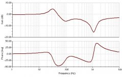
The zobel is in there for both graphs in post #42 and post #49.
It does prevent some peaking after the notch without it.
I cannot see why levels above the notch should be lower.
🙂/sreten.
no zobel, 1R series (100R notch damping resistor)
Attachments
Hi Sreten,
In real life the driver output would be reduced above whatever 'breakup' frequency the notch is tuned to.
Also the driver with Zobel becomes a potential divider in series with its chosen series inductor plus capacitor, so some electrical reduction too without excessive phase change with respect to the mid/FR driver.
Cheers ...... Graham.
Last night I made some measurements with the Woofer Tester to the woofers on baffle with/without T-bass. Quite interesting.
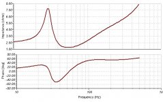
This is 2 Eminence SigmaPro18 on baffle, measured with existed long and thin cables:
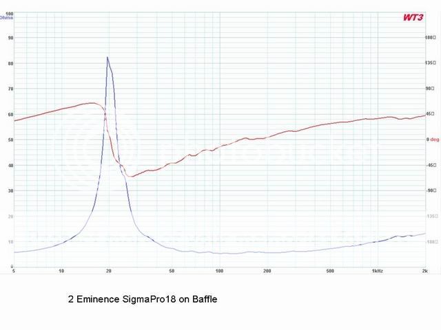
The numbers on axis might not be clear enough, the impedance peak is at 19.51Hz, about 83 Ohm. Re= 4.5 Ohm.
Quite flat 6 Ohm in the range of 60~400Hz. Climbs to 8 Ohm when 50Hz, 10 Ohm when 40Hz, 16 Ohm when 30Hz, and then rush to the peak.
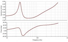
And this is with T-bass (C=10000, L=4.5mH. no series R, no LP section after T-bass, no zoble):
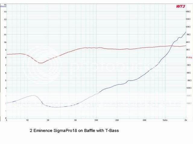
The impedance between 20~40Hz is below 1.6 Ohm. Lowest point is at 26Hz, 1.4 Ohm !! Climbs to 3.2 Ohm at 100Hz, 4.4 Ohm at 200Hz... System Fs moves down to 12.1Hz with a 3 Ohm "peak".
So it does suck a lot of current at the range where the original does not. And that <2 Ohm load at the range of 16~55Hz must load my tube amp as hell😱
I guess decreasing the C should lift the overall too low of impedance at that range, but no proper parts on hand now, sorry.
..... More to come, to be continued....
This is 2 Eminence SigmaPro18 on baffle, measured with existed long and thin cables:
The numbers on axis might not be clear enough, the impedance peak is at 19.51Hz, about 83 Ohm. Re= 4.5 Ohm.
Quite flat 6 Ohm in the range of 60~400Hz. Climbs to 8 Ohm when 50Hz, 10 Ohm when 40Hz, 16 Ohm when 30Hz, and then rush to the peak.
And this is with T-bass (C=10000, L=4.5mH. no series R, no LP section after T-bass, no zoble):
The impedance between 20~40Hz is below 1.6 Ohm. Lowest point is at 26Hz, 1.4 Ohm !! Climbs to 3.2 Ohm at 100Hz, 4.4 Ohm at 200Hz... System Fs moves down to 12.1Hz with a 3 Ohm "peak".
So it does suck a lot of current at the range where the original does not. And that <2 Ohm load at the range of 16~55Hz must load my tube amp as hell😱
I guess decreasing the C should lift the overall too low of impedance at that range, but no proper parts on hand now, sorry.
..... More to come, to be continued....
Needs the right value Capacitor with some series Resistance though !!!
Also SS amp with thick cables for best reproduction.
Also SS amp with thick cables for best reproduction.
CLS said:
I guess decreasing the C should lift the overall too low of impedance
at that range, but no proper parts on hand now, sorry.
No it will not.
The minimum impedance is determined by the two 1 ohm resistors.
SimontY said:Wow, it really deals with driver resonance!
That is a highly debatable statement, as the impedance no longer
reflects the current through the bass driver for voltage drive.
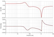
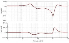
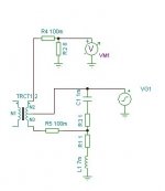
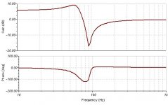
Its an interesting circuit. See attachment.
If you consider the low frequencies and then the high frequencies,
you should be able to see a phase inversion, which means at
some point you will get a cancellation notch, around 90Hz.
Reducing the 1R resistors makes this very apparent.
As well as the phase reversal there is an ~ 6dB gain change.
It is a form of elliptical / cauer filters and can be done actively.
🙂/sreten.
Attachments
Is such a narrow band of very low impedance going to be a potential issue in the real world? Maybe an amp will want to shut down if told to play a very loud 90hz sine wave, but otherwise... any problems?
Thanks
Simon
Thanks
Simon
- Home
- Loudspeakers
- Full Range
- 'T'-bass drive for OB LF drivers.