Hi Fredos,
phantastic device. The body diode is a beauty and gate charge at 170V will be significantly less than with IRFP4668.
IGBTs are coming better and better. I remember a 1kV full bridge in work with 1200V IGBTs. Design was a soft switching ZCS. This crazy thing was sloping the 1kV within 10ns... and without ringing or overshoot..... dv/dt factor two beyond the spec of the high side driver, but the entire system was still forgiving 😀 ...wonders happen.
Current tail of IGBTs could generally be an issue.
fgh40n60smd has not a bad current tail, but the long turn OFF delay will give us some headache for deadtime adjustment with the IRS20957. Also the forward voltage drop behavior of IGBTs will most likely give me some homework to fit it with the OCP.
But it is a tempting option to consider again a design without series diode and without external freewheeling diode... The low Qrr of the diode is really great, even if not specified at 800A/us, but at 100 & 200A/us only.
...thinking about it...
Do you see further key properties?
yep! current capacity... of course, design will be a bit less efficient than mosfet at low power, but a high power, advantage are clear... already got 10 on hand, already drop a pair in a conventional class d at 300khz... work very well with no other adjustment than dead time... this device is like a mosfet on steroid!
Figure 20 in datasheet states just 20A @100C for 300khz , a bit less. But the device looks promising.
Last edited:
I am coming the conclusion that it is not the right device for my plans, despite that it's amazing.
Why not the right thing for my plans?
At first glance it looks like it would fit for a halfbridge which is running from +/-200..220V and could deliver 2kW into 8R unbridged.
But it cannot - at least not at 300kHz and never ever with the additional hard switching topic. Have a closer look to the switching losses. Already without the Qrr issue there is trouble visible. Then draw a picture with Uce and Ic when switching hard into the body diode. Calculate energy areas with 400V rails and 30A. Sum up areas. Multiply with frequency... Life is bad.
Furtheron I would not feel comfortable to invite the DIY world to this voltage level.
Further reasons- independent from the voltage level:
The OCP and dead time adjustment would need to be adressed separately which is adding by far more complexity than what is simplified in the power stage.
The Qrr is stunning for a 600V body diode, but still factor 2 worse than HFB35HB20 and even more far from matching MBR40250TG or V30200C.
==> Impact on THD (but most likely not catastrophic).
Influence of current tail on THD unknown, could be bad or good.
I' ll keep the device in mind for other applications, but for this thread I definitely think I will stay with 200V MosFets and diodes.
Choco I think your app is a bridge running only on +/-80VDC? At this voltage level and >300kHz, it is no wonder that a 600V IGBT can not compete to latest MosFET technology..
Yupp.
That's why I also considered (second block of posting above) the situation to use the device at a reasonable voltage level of 400-440V, but it turns out that switching losses are to high for 300kHz operation with tough load.
That's why I also considered (second block of posting above) the situation to use the device at a reasonable voltage level of 400-440V, but it turns out that switching losses are to high for 300kHz operation with tough load.
Hi Fredos,
can you show more details of the amp and your measurements?
Steroid... there is already to much of it on this world.
can you show more details of the amp and your measurements?
Steroid... there is already to much of it on this world.
Just some sidenote: I have some APT 1200V inverter IGBTs in a full bridge running at 20kHz from a 630Vdc bus. It works well for subwoofer use at some serious power level, but I don't think they can do 300kHz.. lol...
😀 serious power level 😀
630V bus?
Clipping at 550V?
8 Ohms?
18.9kW? 😀😀😀
May the Force be with you.
630V bus?
Clipping at 550V?
8 Ohms?
18.9kW? 😀😀😀
May the Force be with you.
Clipping at 630V, only stable at 16 Ohms and above..
http://www.diyaudio.com/forums/class-d/87913-class-d-amp-photo-gallery-23.html#post2170396
page 23 of the thread: my "tiny" IGBT amplifier
http://www.diyaudio.com/forums/class-d/87913-class-d-amp-photo-gallery-23.html#post2170396
page 23 of the thread: my "tiny" IGBT amplifier
Sorry Baga, but no freewheeling diode, slower turn off time and still only 40A at 300Khz... Better to go with a 300V mosfet and schotky at that point...
...well, better no body diode rather than a poor body diode.
But as already said by fredos, to much switching losses - even without Qrr topic.
But as already said by fredos, to much switching losses - even without Qrr topic.

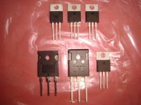
...unpacking component deliveries feels like x-mas
The Beauty And The Beast.
The picture is making the advantage in geometry more obvious.
Nevertheless I have not given up on designing the layout for TO-247 and TO-220 as well.
Looks good how much did you pay for these. 😀
 from my credit card.

Ok, Ok. Just joking. Have to pay the balance on my own.
...always have been a crazy nerd and always have spend most of my money on countless electronic components. But it is easy to count my shoes.
The triple of beauties in TO-220 was around 10,- USD + taxes.
The monster triple was much costlier.
Cannot exactly say the price, because it is partially from my older assortment.
But already the MBR7030 was about 7...8 EUR. 😱
Hey choc
I tried another modulator scheme, I didn't get chance to try the modulation Charles proposed. See below might attempt this for a lower power applications > 1kw
Thanks
I tried another modulator scheme, I didn't get chance to try the modulation Charles proposed. See below might attempt this for a lower power applications > 1kw
An externally hosted image should be here but it was not working when we last tested it.
An externally hosted image should be here but it was not working when we last tested it.
Thanks
Last edited:
- Home
- Amplifiers
- Class D
- SystemD_2kW, any interest for an open design?