Oh really?
Why the hell did I populate it at the first time?
And where did I found the information at the first time?
Ok, simply confused, but tomorrow is power-on-time 😀
Why the hell did I populate it at the first time?
And where did I found the information at the first time?
Ok, simply confused, but tomorrow is power-on-time 😀
Would this whole idea also work with the IR4301M to make an ultra compact alternative?
As far as I know the IR4301M is pretty much an IRS2092 with integrated MOSFETS.
Although, you might have to tweak some bits and bobs.
(maybe because of the deadtime and that kind of things)
As far as I know the IR4301M is pretty much an IRS2092 with integrated MOSFETS.
Although, you might have to tweak some bits and bobs.
(maybe because of the deadtime and that kind of things)
Yes and yes. But keep also in mind board area is not dominated by the IRS2092 (or 2092S) and IRFI4212.
Basically it should be possible to transfer the LiteAmp to the IR4301.
But you should make sure that your rails are not higher than +/-35V.
Also you will not get the 2R feature (consequently for size optimization can choose a filter choke with less current capability).
But you should make sure that your rails are not higher than +/-35V.
Also you will not get the 2R feature (consequently for size optimization can choose a filter choke with less current capability).
Btw, what I still don't get in this whole thread is the following.
You're 'complaining' about the bad performance of the "noisy, jittery comparator".
What was the key reason not going for the irs20957 and using a nice dedicated comparator instead?
You're 'complaining' about the bad performance of the "noisy, jittery comparator".
What was the key reason not going for the irs20957 and using a nice dedicated comparator instead?
It is just about complexity.What was the key reason not going for the irs20957 and using a nice dedicated comparator instead?
Have a look to the first posting. The entire project is purely about how to lift a primitive IRS2092-based circuitry to a high performance.
For your proposal, you would not just need a seperate comparator, but also an OPamp in order to implement the integrating gain.
(Well, with some good luck you might be able to skip the coparator and live with the input thresholds of the IRS20957.)
Hi Chocoholic,
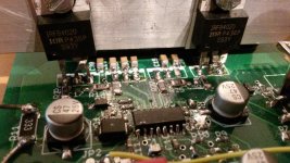
I used your design and build it up in as far as possible in SMD.
The component selection is based on the 2x 80V version.
The stabilisation transistors are MJD340 and MJD350.
I used Polyphenylene Sulphide capacitors instead of the normal trough hole Polypropylene film capacitors
I planned to use 2 single IRFB4020PBF FET instead of your dual FETS.
However, it won't oscillate.
The voltage on VAA and VSS are 4.73 and -4.72 respectively referred to ground.
The OCSET is 1.25V referred to -PWR
VB is 14.97V referred to VS
CSH is 5.97V referred to VS
VCC is 11.46V referred to -PWR
I didn't mount the FETs yet.
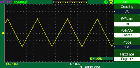
The waveform on the CSD pin is triangular and swinging between approx -2V to +2V (see picture)
It seems like it will not become in normal mode, so oscillation will not start. I couldn't find any aspects what the IRS2092 should decide to hold in shutdown.
Do you have any idea?

I used your design and build it up in as far as possible in SMD.
The component selection is based on the 2x 80V version.
The stabilisation transistors are MJD340 and MJD350.
I used Polyphenylene Sulphide capacitors instead of the normal trough hole Polypropylene film capacitors
I planned to use 2 single IRFB4020PBF FET instead of your dual FETS.
However, it won't oscillate.
The voltage on VAA and VSS are 4.73 and -4.72 respectively referred to ground.
The OCSET is 1.25V referred to -PWR
VB is 14.97V referred to VS
CSH is 5.97V referred to VS
VCC is 11.46V referred to -PWR
I didn't mount the FETs yet.
The waveform on the CSD pin is triangular and swinging between approx -2V to +2V (see picture)
It seems like it will not become in normal mode, so oscillation will not start. I couldn't find any aspects what the IRS2092 should decide to hold in shutdown.
Do you have any idea?
The CSD is typical for a system, which tries to start, but immediately triggers a shut down function.
Pretty likely the IRS will start to generate a gate signal, but then there
is no power device, consequently the Vds will not become small within a few hundret nano seconds. ...well, and that's exactly how the overcurrent protection of all the modern IRS drivers work.
They examine if Vds of the power device reaches a voltage below the shut down level within a few hundrets ns after the gate signal is generated . Without power device Vds will typically remain higher than the shut down level and the IRS is reading this as over current.
Have a look to the gate drive output of the low side. If there you find one short gate pulse (likely shorter than 1us) at the beginning of every CSD cycle and then stops again, then it acts like one can expect without power devices.
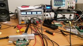
When you power up the first time with power devices, you should use a supply with current limiter. Reasonable settings for the current limiter would be 200mA...500mA.
If you do not have a suitable supply with adjustable current limiter then put serial 100R (2W or stronger) in +80V and -80V.
Last but not least:
If you use one pair of IRFB4020 instead of two paralleled IRFI4020 then later on you will need to readjust the overcurrent shut down level, because of the higher Rdson of your arrangement. But that's more a question for full power operation and it is usually OK to begin with a sensitive setting as you have now.
Pretty likely the IRS will start to generate a gate signal, but then there
is no power device, consequently the Vds will not become small within a few hundret nano seconds. ...well, and that's exactly how the overcurrent protection of all the modern IRS drivers work.
They examine if Vds of the power device reaches a voltage below the shut down level within a few hundrets ns after the gate signal is generated . Without power device Vds will typically remain higher than the shut down level and the IRS is reading this as over current.
Have a look to the gate drive output of the low side. If there you find one short gate pulse (likely shorter than 1us) at the beginning of every CSD cycle and then stops again, then it acts like one can expect without power devices.
When you power up the first time with power devices, you should use a supply with current limiter. Reasonable settings for the current limiter would be 200mA...500mA.
If you do not have a suitable supply with adjustable current limiter then put serial 100R (2W or stronger) in +80V and -80V.
Last but not least:
If you use one pair of IRFB4020 instead of two paralleled IRFI4020 then later on you will need to readjust the overcurrent shut down level, because of the higher Rdson of your arrangement. But that's more a question for full power operation and it is usually OK to begin with a sensitive setting as you have now.
Hi,
Thanks for your answer. It really helps me. I found the problem, drain and source of my FETs were not connected in the correct way. That's why the supply was shorted every time (body diode).
The circuit is up and running.
Hopefully it will perform as good as yours Chocoholic!
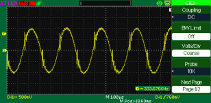
The last picture you see is the output ripple with input shorted.
with speaker connected I can only hear some soft hiss when I place my ear within 10cm from the speaker.
In the future I want to use 2 FETs a side and try to make the circuit suitable for 4 ohms load with double 80V supply.
From now I will try to do some measurements and post the results here.
Thanks for your answer. It really helps me. I found the problem, drain and source of my FETs were not connected in the correct way. That's why the supply was shorted every time (body diode).
The circuit is up and running.
Hopefully it will perform as good as yours Chocoholic!
The last picture you see is the output ripple with input shorted.
with speaker connected I can only hear some soft hiss when I place my ear within 10cm from the speaker.
In the future I want to use 2 FETs a side and try to make the circuit suitable for 4 ohms load with double 80V supply.
From now I will try to do some measurements and post the results here.
Attachments
Just for my understanding:
Your screen shots in posting #468 are without MosFets?
(Because with MosFets inserted and wrong drain source polarity your rails would be shorted and you would not get the internal supplies right and also no CSD cycling).
...and when you tried to run it with MosFets you got shortened rails and because of the drain source polarity, and now with your 'progressive preforming of the pins' 😉 it is running.
Screen shot in #470:
Hm, the carrier at the output shows pretty some blips.
Typically this is caused or worsened by:
- Measurement with long GND clips
- Large half bridge loop
- Incorrectly tuned snubbering
- Short dead time
Nevertheless, my congratulations that you made your own PCB running !
Enjoy 🙂
Just for my understanding:
Your screen shots in posting #468 are without MosFets?
(Because with MosFets inserted and wrong drain source polarity your rails would be shorted and you would not get the internal supplies right and also no CSD cycling).
Yes, thats right.
...and when you tried to run it with MosFets you got shortened rails and because of the drain source polarity, and now with your 'progressive preforming of the pins' 😉 it is running.
Screen shot in #470:
Hm, the carrier at the output shows pretty some blips.
Typically this is caused or worsened by:
- Measurement with long GND clips
- Large half bridge loop
- Incorrectly tuned snubbering
- Short dead time
Nevertheless, my congratulations that you made your own PCB running !
Enjoy 🙂
Thank you!
During the first test, I shorted R26, but now it is opened. The picture below is measured directly on the speaker terminals. But you can see the very small blips again.
I'm not very happy with the amount of noise. With my visaton DX10 test loudspeaker it is not audible 1m away from the unit, but if I use such circuit to amplify my 112dB/w/m HF drivers directly, it could be annoying.
Is that normal or should I look further into the PCB layout for improvements?
... to amplify my 112dB/w/m HF drivers directly, it could be annoying.
Is that normal or should I look further into the PCB layout for improvements?
In order to judge if your set up is already touching the limitations of the IRS2092 or is suffering too much from other noise reasons (like layout) I would need to see a proper noise measurement. A high order (at least 5th order, preferably 6th) low pass filter with approx 16kHz...20kHz -3db bandwidth followed by a low noise gain stage with a voltage gain of at least 200, but preferably 500 or 1000. With this you can make the noise visible on any scope. Use a time scale of 2ms or 5ms per grid. Measure the peak2peak value. Anticipating a white noise you can derive the rms value by dividing the peak2peak value by factor 6.
The blibs on the output do not necessarily translate into audible noise. With some good luck you are just blasting EMI emissions into the world, without causing issues to your own circuit. But also EMI emissions not desirable and for good reasons there are limitations by law.
In general I have to state that there is no clue in running 112dB/w/m HF drivers from a +/-80V supplied high power amplifier in your living room. For this definitely the +/-40V version would be more appropriate and allow 4...5db less output noise.
With correct layout the +/-40V version can achieve an output noise level of approx. 75uVrms, while the +/-80V version will not allow less than 130uVrms.
The purpose for the amplifiers is not a livingroom but for semi-prof audio setups.
just to give you an idea of my choices:
My toughts were to use 2 amplifiers on the same rail. One HF amplifier with only 1 FET a side (I dont need that current there), and two amplifiers bridged for the LF section. So that they share their supply. otherwise, I need to an extra winding on my SMPS transformer.
but thats future.
I will start to do some THD+N measurements with ARTA and a good external soundcard since I have the equipment for it. Are that figures not enough to say something about the noise level?
I will test the HF driver noise as well and post the results here.
..do I get it right? You intend to power a tweeter of an active system with such power? Or means HF just no deep base?
Anyhow. It is possible to run multiple lite amps from a common dual supply.
Curious to see your next steps - and also about your entire system with subs and hf unit.
Anyhow. It is possible to run multiple lite amps from a common dual supply.
Curious to see your next steps - and also about your entire system with subs and hf unit.

😀 The Beyma is a beast. Still an average power limiter might be a good idea when firing with a 300W amp.
Hm, - so you are going to shoot with 300W into a 112db/m system for mid & high.
😱 This is going to be loud at full power... 😱
You will need a pretty efficient woofer in order to reach comparable output levels for the base with the 1200W which one can expect from the bridged amp.
Well, on the other hand there is nothing wrong in using multiple drivers in the sub and fire each of them with 1200W from its own bridged amp.
hey markus long time..
Just an idea for some time this year..
I'm thinking of making a multi channel version of this project (keeping things original) expect for the WIMA caps as a result of local suppliers not keeping stock, and.. changing the layout geometry slightly so the output fets are near the PCB edge.
what sort of power supply are we looking at for a 40V x8-channels ?
This is a cool project.
Are the performance/measurements comparable to the legendary Ncore at similar power rating?
How does the listening impression compare? I am sure similar level of clean, transparent and controlled rendering of recordings
Are the performance/measurements comparable to the legendary Ncore at similar power rating?
How does the listening impression compare? I am sure similar level of clean, transparent and controlled rendering of recordings
It will depend very much on what you intend to do with the 8 chanels?what sort of power supply are we looking at for a 40V x8-channels ?
All full music program or with frequency cross over? Firing 2R, 4R or 8R?
I will assume the toughest, means all of them full range into 2R.
First let's split the peak power from average power.
With p(t)=Up * sin(wt) * Ip * sin(wt) the 400W into 2R will lead to a max instantenous power of 800W peak.
For 8 eight chanels your will need a PSU which can deliver approx 7kW peak (6400W+losses).
The average power with normal music programm will be about 8 times lower.
For PA typically factor 3 is applied.
The ncore will measure better in terms of THD while the lite amp measures better in terms of step response. IMHO both show measurements in all disciplines which are far beyond numbers which would allow to kick out one or the other simply from reading the measurements.This is a cool project.
Are the performance/measurements comparable to the legendary Ncore at similar power rating?
How does the listening impression compare? I am sure similar level of clean, transparent and controlled rendering of recordings
Soundwise...
I must admit, after I found my love in the V1.5 of the 2kW open design, I did not go into extensive listening tests with the lite amp. At first glance it was simply a neutral amp.
In any case I would be biased, so the question of sound should be better answered by other DIYers who heard the amp.
- Home
- Amplifiers
- Class D
- SystemD LiteAmp