Chocoholc, I have a power supply that gives +/- 50V dc. Is that too much for the existing version and will the high power version use the same PCB?
Hi Chienmort,
+/-50V definitely is to much for the 40V version.
Nevertheless I got a similar backstage request some weeks ago.
I have settled a theoretic BOM (using the same PCB) for rails up to +/-55V
and load impedances of 4 Ohms or higher, no 2 Ohms capability.
The 55V version is not tested, theory only - however if you are experienced in electronics and dare to take some R&D risk, you can give it a try.
Attached the 55V-BOM, red marked are all differences vs the 40V version.
Potential 75V version:
Not yet started. In case that will find time to design it, then I will use the same PCB. I do not intend to spend again time for further PCB versions of the lite amp.
Attachments
Here is a good reason to make a +/-55V version - $20 dual rail supplies...
Abletec Switch Mode Power Supply +53V at 1.4A, -53V at 1.4A, +7.5V at 1.6A, +5.6V 1A
These are a fantastic deal in the USA. The specs say they are good for quite a bit of current for 54 volts at 4.13 amps for 5 minutes.
http://www.parts-express.com/pedocs/specs/129-147-parts-express-specifications.pdf
Available in Europe via eBay:
Abletec 900 Watt Peak Class D Audio Amplifier Power Supply 53V DC UL Cul | eBay
Last edited:
Hi Chienmort,
+/-50V definitely is to much for the 40V version.
Nevertheless I got a similar backstage request some weeks ago.
I have settled a theoretic BOM (using the same PCB) for rails up to +/-55V
and load impedances of 4 Ohms or higher, no 2 Ohms capability.
The 55V version is not tested, theory only - however if you are experienced in electronics and dare to take some R&D risk, you can give it a try.
Attached the 55V-BOM, red marked are all differences vs the 40V version.
Potential 75V version:
Not yet started. In case that will find time to design it, then I will use the same PCB. I do not intend to spend again time for further PCB versions of the lite amp.
Thank you very much for the extra work involved. I will let you know of my order later today.
Thank you very much for the extra work involved.
A few hours of theoretic considerations and BOM writing...
Please everybody be aware that I do not intend to build/test/refine the 55V version. This part is up to everybody who wants have this version.
But of course you are welcome to show your experiences and also learnings which I did not foresee from theory. Also in case of questions I will support as far as possible without building it on my own.
Great! Everybody who can build/test/refine, may proceed. I don't have the knowledge, but I may help anyway you want!
A few hours of theoretic considerations and BOM writing...
Please everybody be aware that I do not intend to build/test/refine the 55V version. This part is up to everybody who wants have this version.
But of course you are welcome to show your experiences and also learnings which I did not foresee from theory. Also in case of questions I will support as far as possible without building it on my own.
I understand.
I'm very sorry that I forgot to post last night before the deadline Choco! Is there any possibility to still be added to the list?
Main board x 2
Gain board x 2
NSL x 2
Main board x 2
Gain board x 2
NSL x 2
PCB ordered
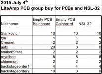
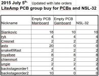
...PCB orders are now placed at the vendor.
The attached table shows all your requests which I took into account.
My thanks to all of you who have given me the shipping adress early and paid fast. Thanks, this helps to keep the org efforts low.
In case you did not pay yet, please do not forget to so in the next days.
Please check your PM for details.
Attachments
Due to the large PCB quantities the vendor costs for transportation&handling are giving much less adder per piece.
Updated correct PCB prices are now:
Mainboard: 1.68 EUR
Gainboard: 1.21 EUR
... remaining unchanged:
NSL-32: 0.88 EUR
Shipping Germany: 3.60EUR
Shipping International: 5.60EUR
To all who already have paid I will transfer back the difference.
All who have not yet paid, please use the new prices.
Updated correct PCB prices are now:
Mainboard: 1.68 EUR
Gainboard: 1.21 EUR
... remaining unchanged:
NSL-32: 0.88 EUR
Shipping Germany: 3.60EUR
Shipping International: 5.60EUR
To all who already have paid I will transfer back the difference.
All who have not yet paid, please use the new prices.
I am sorry if this has been posted already but what is the output power of the amplifier Into 2, 4 & 8 ohms for the standard 40V version? I will be using 36-0-36V.
Also what power for the 50V version?
Also what power for the 50V version?
Regarding electrical requirements the data sheet is looking good.
http://www.elna.co.jp/en/capacitor/alumi/catalog/pdf/rfs_e.pdf
But mechanical size is critical.
My largest intended footprint is for a 17mm diameter.
Your proposed cap is a 18mm type.
The real distance in the PCB is 17.8mm. Means it becomes a matter of tolerances.
With some good luck you will be able to place them properly.
With some bad luck you will need to be creative...
I am sorry if this has been posted already but what is the output power of the amplifier Into 2, 4 & 8 ohms for the standard 40V version? I will be using 36-0-36V.
Also what power for the 50V version?
With stabilized dual 36V rails you can expect:
289W into 2R
146W into 4R
74W into 8R
If your supply is not stabilized but will show sagging, obviously it will be less.
The exact values depend on the sagging behavior of your supply.
Feel free to stroll through the forum and find out what you can expect from your supply.
When you know your rail voltage at full load, you can calculate as shwon below.
As a rule of thumb you can guess that you drop 0V...3V (say 2V) in the MosFets, output choke, copper tracks and wiring.
Just follow Ohms law and consider sinusodial wave shapes which are clamped 2V below the rail.
Pout = (Vrail-2V)² / (2* Rload)
For a +/-36V supply please apply Vrail=36V
Considering a 2V drop is OK for the 40V version and 50V as well.
But take care: The 50V version is only suited for 4 Ohms and higher. Not 2 Ohms.
- Home
- Amplifiers
- Class D
- SystemD LiteAmp