Several inquiries over the last 14 years, but no SynTripP are currently being made under my license for sale anywhere in the world.
Art
Art
Is this because people aren't building them commercially or because people aren't willing to pay licensing?
No commercial firm or individual has indicated SynTripP license fees to be a deterrent to manufacture.
Considering nearly every aspect of the SynTripP design could be improved upon, I don't see why a commercially oriented manufacture wouldn't make a similar, but better product if they were interested in pursuing the particular niche market it appeals to.
Art
Considering nearly every aspect of the SynTripP design could be improved upon, I don't see why a commercially oriented manufacture wouldn't make a similar, but better product if they were interested in pursuing the particular niche market it appeals to.
Art
Hello.
I was fascinated by your production of SynTripP and decided to try to make one myself.
First of all, thank you FartyMcfly for sharing the data.
The data here was very helpful!
After going through the past posts, I decided to rebuild it in Fusion360 based on the onshape model by Losandstrom in #1135. Very much appreciate the data sharing here as well.
The stock at the parts supplier did not have 10CL51 in stock, so we decided to build it with 10CLA64 instead.
(As a side note, I heard that they will be stocked for the next production, so I plan to try 10CL51 at that time.)
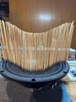
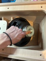
We knew that the center cap size of 10CLA was different from that of 10CL51, but when we received it, we realized that the shape itself was different.
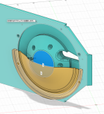
For this reason, we decided to redesign the cone filler section.
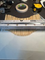
Using a bamboo stick, we took simple measurements, dropped them onto a drawing and re-printed it several times to roughly match the shape.
I then looked at past posts and decided that the clearance between the cone and the cone filler section should be about twice the Xmax.
I modeled it like this on 3D CAD. Is the idea correct in terms of shape?
These are basically just changes to the cone filler section so that they can be changed to 10CL51.
I was fascinated by your production of SynTripP and decided to try to make one myself.
First of all, thank you FartyMcfly for sharing the data.
The data here was very helpful!
After going through the past posts, I decided to rebuild it in Fusion360 based on the onshape model by Losandstrom in #1135. Very much appreciate the data sharing here as well.
The stock at the parts supplier did not have 10CL51 in stock, so we decided to build it with 10CLA64 instead.
(As a side note, I heard that they will be stocked for the next production, so I plan to try 10CL51 at that time.)
We knew that the center cap size of 10CLA was different from that of 10CL51, but when we received it, we realized that the shape itself was different.
For this reason, we decided to redesign the cone filler section.
Using a bamboo stick, we took simple measurements, dropped them onto a drawing and re-printed it several times to roughly match the shape.
I then looked at past posts and decided that the clearance between the cone and the cone filler section should be about twice the Xmax.
I modeled it like this on 3D CAD. Is the idea correct in terms of shape?
These are basically just changes to the cone filler section so that they can be changed to 10CL51.
Attachments
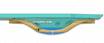

Filler shape looks correct for the 10CLA64 cone.Is the idea correct in terms of shape?
Parts look good!
Art
Good morning Art,Filler shape looks correct for the 10CLA64 cone.
Parts look good!
Art
Thanks to you, I can proceed with our work with peace of mind!
Well, depends on your definition of "peace of mind" 😉Thanks to you, I can proceed with our work with peace of mind!
SynTripP© Syn·Trip·P (sĭn'trip-ē) n. The occasional tendency of two or more mental diseases to coalesce into one resembling or inducing the hallucinatory effect produced by taking a psychedelic compound.
I remember how excited I was when I read the beginning of this thread.Well, depends on your definition of "peace of mind" 😉
SynTripP© Syn·Trip·P (sĭn'trip-ē) n. The occasional tendency of two or more mental diseases to coalesce into one resembling or inducing the hallucinatory effect produced by taking a psychedelic compound.
I would really like to be able to achieve such a state only by the tone of the speakers!
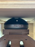
Assembled for the moment, the clearance of the unit seems to be fine.
The tweeter is also not touched.
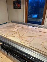
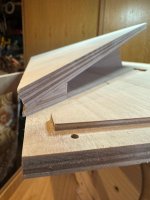
My CNC makes it fairly easy to assemble.
The rear opening is narrow to make it as strong as possible.
Attachments
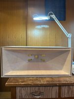
Final assembly time. Everything dry fits really nicely so it's glue and screw and sealant next. Still need to make a rear panel and wire it up but could be sound testing v soon!


It's very cool and inspiring to see so many great SynTripP builds come together lately!
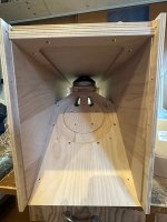
I've managed some small progress with my own, completing a dry fit to check alignment of the 3d printed horn within the cabinet. Its slightly gappy so I'm considering using a construction adhesive to achieve up to a mm or two of strong fill between the cabinet panels and the attachment points of the PETG horn. Wondering if that's the most suitable product?


I've managed some small progress with my own, completing a dry fit to check alignment of the 3d printed horn within the cabinet. Its slightly gappy so I'm considering using a construction adhesive to achieve up to a mm or two of strong fill between the cabinet panels and the attachment points of the PETG horn. Wondering if that's the most suitable product?
Thanks @crumpets, were you thinking a two part automotive body filler for sealing/filling or more like an epoxy glue? 🙂I'd use epoxy/filler
Hi all,
Greetings from London.
Long time lurker here, I am getting wood cut early May to start building a pair of SyntripP. Wish me luck !
I got the throat adapters and the cone fillers and I am now familiar enough with the plans to get started.
One thing though I couldn't find yet is a scheme for the wiring. If I am ok with woodwork, I am a bare rookie on electric/wiring.
Any good soul here to explain our to wire it properly ?
If it was discussed in this thread before, I didn't find it and keen to be directed to the right previous posts.
My other query about damping material just got answered recently thanks to Octapotamus !
Thanks in advance.
Florent
Hey @FloKai !
Woofers wired in parallel (+ & - on discrete conductors) is convention for these I believe.
High frequency driver on a separate plug (I haven't wired that yet).
I'm using 14awg stranded copper for everything. Separate conductors for the internal wiring, and 14/4 SJOOW for the main leads, with Neutrik NL4 connections. I recommend the Wago connectors internally as they're easily disconnected/reconnected if/when one needs to take the back off and repair anything.
P.S. I ended up just going with 1" denim fiber damping, without the mass loading. It was a lot cheaper and I think it'll do the job just fine.
Last edited:
Normally you would wire the woofer with a Speakon NL4MP socket like this:Woofers wired in parallel (+ & - on discrete conductors) is convention for these I believe
low frequency pins 1+/1-
high frequency pins 2+/2
Noice!It's very cool and inspiring to see so many great SynTripP builds come together lately!
I've managed some small progress with my own, completing a dry fit to check alignment of the 3d printed horn within the cabinet. Its slightly gappy so I'm considering using a construction adhesive to achieve up to a mm or two of strong fill between the cabinet panels and the attachment points of the PETG horn. Wondering if that's the most suitable product? View attachment 1450745View attachment 1450743
View attachment 1450746
What settings did you use for your horn body print @rrobot ? And how much filament did you go through?
It's a little while since I finished the printing. As one often does with unpleasant experiences, I've tried to emotionally suppress as many details as possible. 😆 MrSpeakers warned in his first post some years ago that it wasn't a straightforward print and so it proved.What settings did you use for your horn body print
I think I used just short of 2kg per horn half, even at a lowish 20% gyroid in-fill and each half ran for over 3 days. I printed PETG in an enclosure, but the damn thing kept lifting when it got tall and started pulling so the waste was astronomical. I considered the big 5kg spools to avoid the filament change which disrupted the enclosure temps but that was hard to set up optimally. It was just a real pain all round, and don't like to think what it cost me in filament, power and time. I'm hopeful of a good result in the end but worry about resonances with the low in-fill. I've tried to mitigate that with some damping treatment but until I start testing we don't really know. The sensible thing would have been for me to abandon the print altogether but I'm not very smart like that.
I think were I print it now I would definitely klipperise my Solvol SV06 plus or (preferable) buy a better printer, or even use a printer which could fit the whole horn. I'd also chop off the braces and print them separately. I'm incredibly grateful to Art for the design and to MrSpeakers for sharing his printable STLs but have no plans to print one again as I found it extremely challenging. If you have a big, fast, enclosed machine you'll do a lot better. As others including Art have discussed (and indeed are doing in the many excellent MEH projects cropping up) a good plan would probably be to design and print "stubs" onto which wooden horn sections and bracing can be secured, and to save the 3d printing for the compound curves like the throat transition or the ports. That said, printers are improving all the time and wood/CAD time is just getting more expensive so it's probably a more economic proposition with newer equipment. I don't want to deter you, but just go in with eyes open! 🙂
If everything is done by the book, one should be able to connected and disconnected these connecter in a bi-amp config (NL4MP) with amps switch on - right? No worries for any shorts while doing the un-mount twisting action etc?Speakon NL4MP
//
why would you want to do that (connect/disconnect with power on)?
Perhaps that is the reason you chose TNT as your name? 🙂
Perhaps that is the reason you chose TNT as your name? 🙂
If everything is done by the book, one should be able to connected and disconnected these connecter in a bi-amp config (NL4MP) with amps switch on - right? No worries for any shorts while doing the un-mount twisting action etc?
//
No worries, I do it all the time testing stuff. No shorts.
That said, all the amps I do it with are prosound that i know can handle open circuit no prob.
- Home
- Loudspeakers
- Multi-Way
- SynTripP: 2-way 2-part Virtual Single Point Source Horn