I've been intrigued by the Synergy concept for some years but have some resistance against using compression drivers. The very high sensitivity makes them noisy with my amplifiers. But primarily I've gotten really nice results with the ScanSpeak R2604 in a waveguide which makes me want to try it.
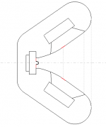
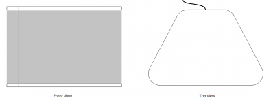
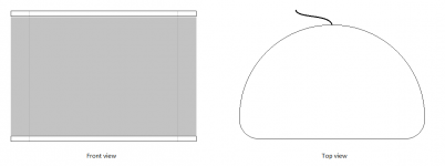
A first sketch:
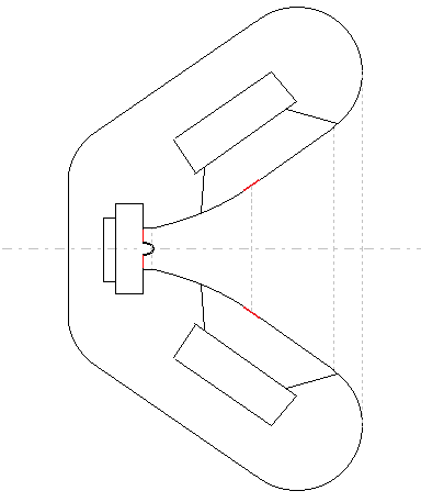
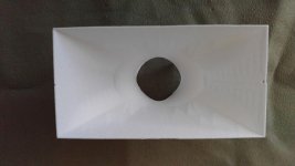
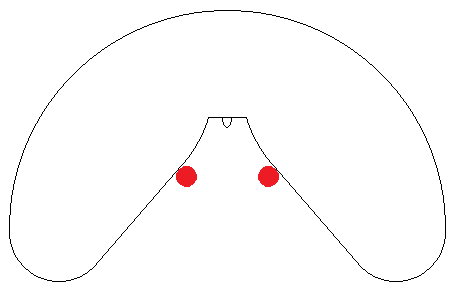
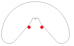
Inside. The woofers are Faital Pro 8FE200.
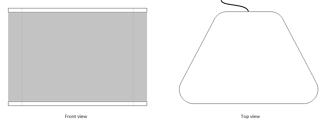
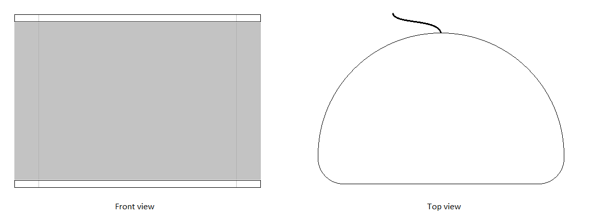
Outside view.
The size is about 50 x 35 x 30 cm (W x H x D, 20" x 13" x 12"), i.e. a quite compact synergy.
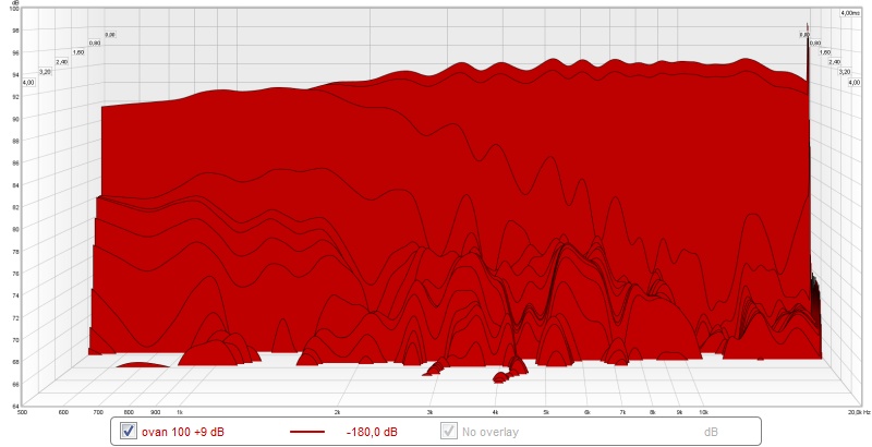
These are the horisontal polars of the R2604 in an early waveguide (210x130x85 mm):

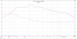
Measured waveguide (the brown one).
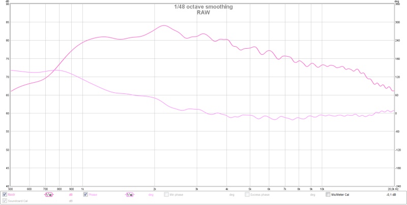
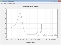
On axis, with phase.
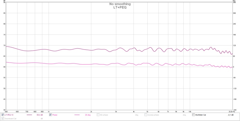
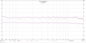
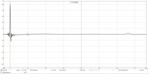
On axis with PEQ and LT.
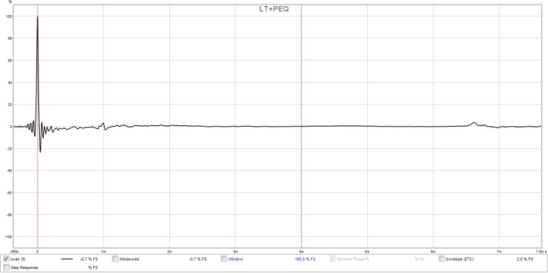
On axis with PEQ and LT.
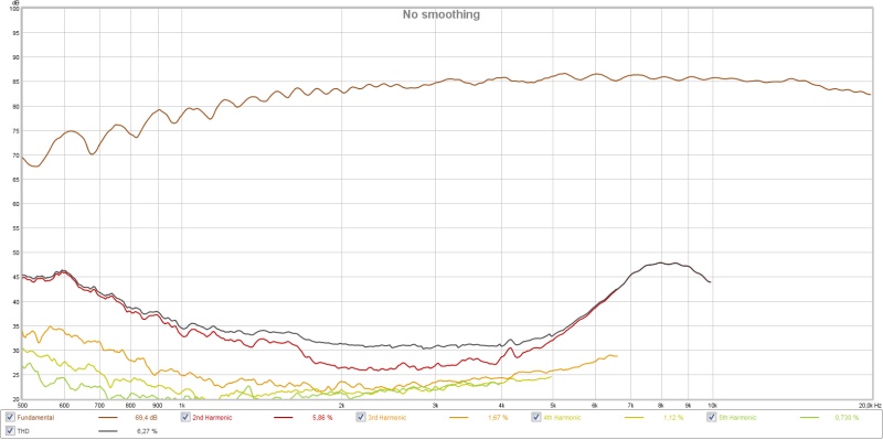
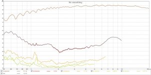
Distortion at 85 dB with 1.2 kHz bessel (for Harsch XO).
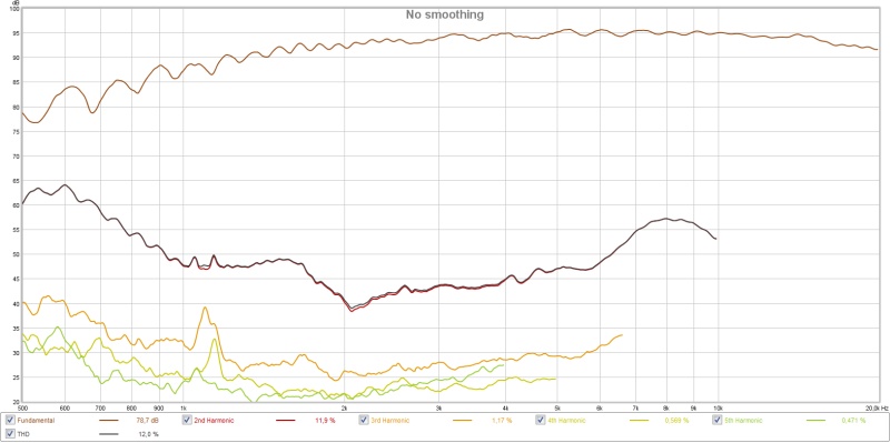
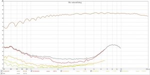
Distortion at 94 dB with 1.2 kHz bessel (for Harsch XO).The R2604 should be better loaded in the bottom end with a 50 cm wide waveguide (synergy horn) and that should reduce the distortion to enable a 1.2 kHz crossover and 95 dB maximum level.
The plan is to 3D-print the first part of the horn (throat) and then use wood for the last part.
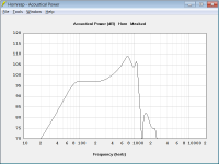
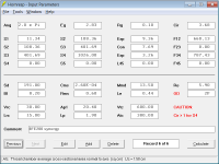
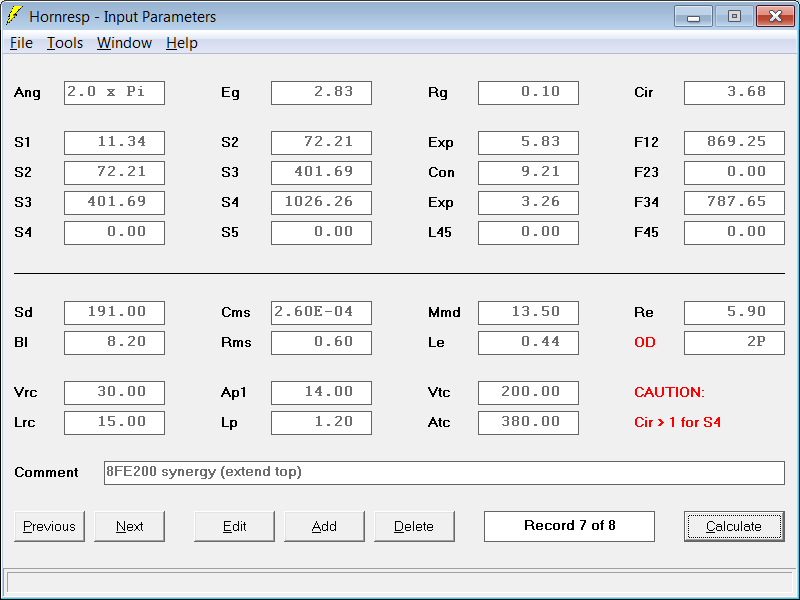
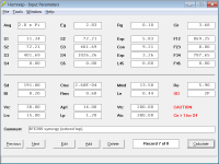
I'm quite new to Hornresp, but have tried a little:

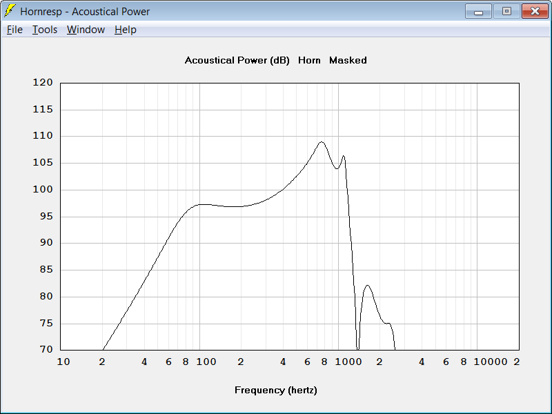
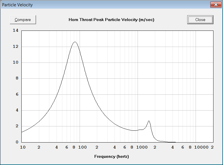
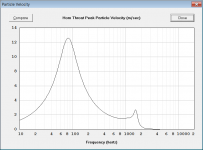
Throat velocity (separate model) is 9 m/s at 2.83 V and diaphragm displacement is 1 mm. I've used 2 x 1" holes for each woofer in 19 mm MDF using minimal volume filler (measured the Vtc for the woofers at 350 ml).
The plan is also to have a leaky supercardioid setup for the woofers to stretch the directivity of the speaker down to below 200 Hz.
I'll post 3D-models later to show what I plan to print 🙂
/Anton
A first sketch:
Inside. The woofers are Faital Pro 8FE200.
Outside view.
The size is about 50 x 35 x 30 cm (W x H x D, 20" x 13" x 12"), i.e. a quite compact synergy.
These are the horisontal polars of the R2604 in an early waveguide (210x130x85 mm):
An externally hosted image should be here but it was not working when we last tested it.
Measured waveguide (the brown one).
On axis, with phase.
On axis with PEQ and LT.
On axis with PEQ and LT.
Distortion at 85 dB with 1.2 kHz bessel (for Harsch XO).
Distortion at 94 dB with 1.2 kHz bessel (for Harsch XO).The R2604 should be better loaded in the bottom end with a 50 cm wide waveguide (synergy horn) and that should reduce the distortion to enable a 1.2 kHz crossover and 95 dB maximum level.
The plan is to 3D-print the first part of the horn (throat) and then use wood for the last part.
I'm quite new to Hornresp, but have tried a little:
Throat velocity (separate model) is 9 m/s at 2.83 V and diaphragm displacement is 1 mm. I've used 2 x 1" holes for each woofer in 19 mm MDF using minimal volume filler (measured the Vtc for the woofers at 350 ml).
The plan is also to have a leaky supercardioid setup for the woofers to stretch the directivity of the speaker down to below 200 Hz.
I'll post 3D-models later to show what I plan to print 🙂
/Anton
Attachments
-
 r2604 synergy.png6.3 KB · Views: 2,402
 -
 sketch2.png4.8 KB · Views: 2,350
 -
 R2604 WG dist 94dB.jpg73.8 KB · Views: 2,337
 -
 R2604 WG dist 85dB.jpg72.6 KB · Views: 2,262
 -
 R2604 WG LT+PEQ.jpg53.1 KB · Views: 2,288
 -
 R2604 WG raw.jpg52.1 KB · Views: 2,362
 -
 R2604 WG LT+PEQ impulse.jpg48.1 KB · Views: 2,513
 -
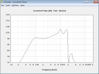
 hornresp power.png17.3 KB · Views: 2,261
 -
 hornresp input.png20.6 KB · Views: 2,280
Last edited:

Nice. 🙂
How are you going to get the woofer bandpass to go past 1k (preferably 2k) in order to have a good overlap with 1k XO for tweeter? The steep cliff at 1k will make it impossible to do, say a Harsch XO at 1k. Or, with a larger WG, you expect the ring radiator dome to go well below 1k?
Will you print the whole thing WG and all? Commercial printer or in pieces then glue together?
I struggled mightily to make 8FE200s work in a 2-way synergy. I could get response out to 1.3 Khz (using a volume plug) but no matter what I did, I had a null around 900 hz. The configuration that minimized this null was with no enclosure around the back of the 8Fe200s and with those drivers draped with absorption. That was how I prototyped it but my celebration was premature.
Like you, I was trying for a small, tight box for each 8FE200, just big enough to fit the magnet and with the back wall of the box parallel to the horn wall. My conclusion was that reflections from the back wall were arriving 180 degrees out of phase at the port through the horn wall and cancelling. Others have shown successful use of the 8FE200 in larger enclosures. My advice is make sure you have enough space behind the drivers for enough absorption to absorb the back wave at the resonant distance.
Like you, I was trying for a small, tight box for each 8FE200, just big enough to fit the magnet and with the back wall of the box parallel to the horn wall. My conclusion was that reflections from the back wall were arriving 180 degrees out of phase at the port through the horn wall and cancelling. Others have shown successful use of the 8FE200 in larger enclosures. My advice is make sure you have enough space behind the drivers for enough absorption to absorb the back wave at the resonant distance.
Good point! I'll probably need to print volume fillers as well. One upside of using the R2604 is that the membrane is in the horn throat and not deep inside a driver, so the notch from the reflection should be high in frequency.Nice. 🙂
How are you going to get the woofer bandpass to go past 1k (preferably 2k) in order to have a good overlap with 1k XO for tweeter? The steep cliff at 1k will make it impossible to do, say a Harsch XO at 1k. Or, with a larger WG, you expect the ring radiator dome to go well below 1k?
Will you print the whole thing WG and all? Commercial printer or in pieces then glue together?
I'll print the throat, maybe first 7-8 cm.
/Anton
very interesting work. I also share interest in extrapolating on Synergy approach and was thinking of inserting a tweeter in the back of this horn which Hoerst did with Visaton B200:
Horn-Sat
not quite sure how something like that could be done but the thought crossed my mind when I was messing with playing B200 through cardboard boxes (when breaking it in for use in my OB), and that driver does classical music and deeper voices like you would not believe it. but off a flat baffle and run FR it is just awful.
if there was a way geomerically to combine two drivers in a horn where the back radiaton is adding to the front outputs for increased sensitivity, that could also be interesting for CD use.
Last edited:
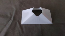
re' just printing the throat
I've done a rectangular wooden conical horn synergy with a square throat from BWaslo's spreadsheet. I did the round to rectangular conversion with modelling clay like most others. Unsatisfied with this and inspired by XRK's thread I just 3D printed an insert for the horn that does that conversion much more smoothly than I did with clay. Now I've got to scrape off the clay and slide the adapter back into the throat in its place and measure to see what improvement I got.
I think this insert approach is easier to execute than joining a wood section to a plastic printed section, provided one is comfortable working with wood in the first place. The hard part, for me at least, was doing the CAD for the adapter and prior to that, choosing an appropriate profile. I did this in Sketchup and generated the shape heuristically rather than mathematically. It looks a little rougher than it actually is or I would like but is at least a proof of concept. I just exported STL from the Sketchup drawing and sent it and $30. off to "Sculpteo". I felt very lucky when I got the piece back a few days later.
Some pictures below. The adapter is roughly 2" by 3.7" by 1.5" for a 90x45 horn. The third image is the google file itself showing the adapter in the horn. It ends about .5" short of the mid ports with final thickness of perhaps 1/32".
Attachments
Alright, I'm going for a leaky cabinet and maybe there is a point in putting the vents directly behind the drivers.I struggled mightily to make 8FE200s work in a 2-way synergy. I could get response out to 1.3 Khz (using a volume plug) but no matter what I did, I had a null around 900 hz. The configuration that minimized this null was with no enclosure around the back of the 8Fe200s and with those drivers draped with absorption. That was how I prototyped it but my celebration was premature.
Like you, I was trying for a small, tight box for each 8FE200, just big enough to fit the magnet and with the back wall of the box parallel to the horn wall. My conclusion was that reflections from the back wall were arriving 180 degrees out of phase at the port through the horn wall and cancelling. Others have shown successful use of the 8FE200 in larger enclosures. My advice is make sure you have enough space behind the drivers for enough absorption to absorb the back wave at the resonant distance.
Sure looks easier! My approach will however be very sensitive towards shape of the throat as the wave is in no way flat when entering the horn compared to a (good) compression driver. The R2604 is however quite light, which should make the connecting easier.re' just printing the throat
I've done a rectangular wooden conical horn synergy with a square throat from BWaslo's spreadsheet. I did the round to rectangular conversion with modelling clay like most others. Unsatisfied with this and inspired by XRK's thread I just 3D printed an insert for the horn that does that conversion much more smoothly than I did with clay. Now I've got to scrape off the clay and slide the adapter back into the throat in its place and measure to see what improvement I got.
I think this insert approach is easier to execute than joining a wood section to a plastic printed section, provided one is comfortable working with wood in the first place. The hard part, for me at least, was doing the CAD for the adapter and prior to that, choosing an appropriate profile. I did this in Sketchup and generated the shape heuristically rather than mathematically. It looks a little rougher than it actually is or I would like but is at least a proof of concept. I just exported STL from the Sketchup drawing and sent it and $30. off to "Sculpteo". I felt very lucky when I got the piece back a few days later.
Some pictures below. The adapter is roughly 2" by 3.7" by 1.5" for a 90x45 horn. The third image is the google file itself showing the adapter in the horn. It ends about .5" short of the mid ports with final thickness of perhaps 1/32".
This is from a simulation I've done of a WG that should perform better than the one I've measured:
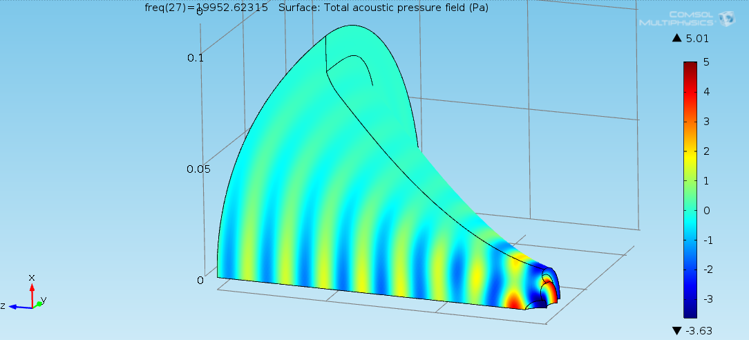
Simulated result:
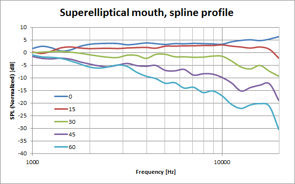
Constant directivity from 2 kHz to 10 kHz. The low end should improve with a larger WG.
/Anton
New hornresp attempt
I tried to get the response for the 8FE200 up to 2 kHz and arrived here:


I've assumed that the throat adapter only needs to be 5 cm long. I also reduced the holes to 21 mm diameter (from 25.4 mm). Looks like this:
Probably even better to make them oblong from diffraction point of view, but that reduces the possible length of the throat adaptor.
Another possible look:
/Anton
I tried to get the response for the 8FE200 up to 2 kHz and arrived here:
I've assumed that the throat adapter only needs to be 5 cm long. I also reduced the holes to 21 mm diameter (from 25.4 mm). Looks like this:
Probably even better to make them oblong from diffraction point of view, but that reduces the possible length of the throat adaptor.
Another possible look:
/Anton
Attachments
that looks very doable. You wouldn't get the same results using a compression driver, because, as you said, you'd have to add perhaps another 3 cm to the reflection distance. The L12 on my 8FE200 proto was 2.25" which suggest that your 5.8 cm is practical.
I noticed in doing these horn response sims that if, for example, you changed both your "Ap1" and "Lp" parameters to half the values in your posted model, you would get the same results - both for the frequency response curve and the offset throat particle velocity. If you can thin out the horn wall at the port location (e.g. frustrumize), then you can use a smaller hole and thus better polars If one takes this to the extreme, you end up with an extremely thin horn wall and an extremely small hole. What is the catch?
I noticed in doing these horn response sims that if, for example, you changed both your "Ap1" and "Lp" parameters to half the values in your posted model, you would get the same results - both for the frequency response curve and the offset throat particle velocity. If you can thin out the horn wall at the port location (e.g. frustrumize), then you can use a smaller hole and thus better polars If one takes this to the extreme, you end up with an extremely thin horn wall and an extremely small hole. What is the catch?
One thing I wanted to ask given your comment about the shape of the wave entering the horn from the ring radiator tweeter - are you able to model that so as to accurately predict the polar response of the horn driven by that tweeter?
An extremely thin horn wall would imply a larger VTC (volume of throat chamber). The VTC needs to be filled to reduce it's volume to raise the mid driver's upper cut off frequency high enough for the tweeter to not run out of excursion in it's lower range.If you can thin out the horn wall at the port location (e.g. frustrumize), then you can use a smaller hole and thus better polars If one takes this to the extreme, you end up with an extremely thin horn wall and an extremely small hole. What is the catch?
Last edited:
Interesting find indeed! I had to do a control myself cause it seems weird, a smaller hole should result in higher particle velocity.that looks very doable. You wouldn't get the same results using a compression driver, because, as you said, you'd have to add perhaps another 3 cm to the reflection distance. The L12 on my 8FE200 proto was 2.25" which suggest that your 5.8 cm is practical.
I noticed in doing these horn response sims that if, for example, you changed both your "Ap1" and "Lp" parameters to half the values in your posted model, you would get the same results - both for the frequency response curve and the offset throat particle velocity. If you can thin out the horn wall at the port location (e.g. frustrumize), then you can use a smaller hole and thus better polars If one takes this to the extreme, you end up with an extremely thin horn wall and an extremely small hole. What is the catch?
/Anton
Well, I'm trying as apparent in the 3D-printing thread (starting at post 174 here).One thing I wanted to ask given your comment about the shape of the wave entering the horn from the ring radiator tweeter - are you able to model that so as to accurately predict the polar response of the horn driven by that tweeter?
Here is comparison of measured and simulated horisontal polar response for the brown WG:
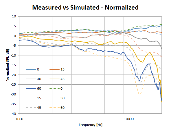
I discuss sources for discrepancies in the thread.
Hopefully I can make a model of the synergy later.
/Anton
It does indeed seem counter intuitiveInteresting find indeed! I had to do a control myself cause it seems weird, a smaller hole should result in higher particle velocity.
/Anton
. if using a volume plug you may end up with a longer port length and need a larger hole.
Last edited:
I tried to get the response for the 8FE200 up to 2 kHz and arrived here:
Have you tried using the Multiple Entry Horn Loudspeaker Wizard to simulate the complete system rather than just the offset drivers? See the Hornresp Help file for details.
Attachments
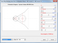
A very interesting addition, especially for a passive three-way. I'm going active though and see no difference in simming as an offset horn.Have you tried using the Multiple Entry Horn Loudspeaker Wizard to simulate the complete system rather than just the offset drivers? See the Hornresp Help file for details.
/Anton
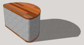
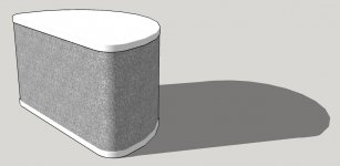
Sketchup model
Played around a little in Sketchup. Outer dimensions are 50 x 28.2 x 30 cm and the waveguide mouth is thereby 40 x 25 cm.
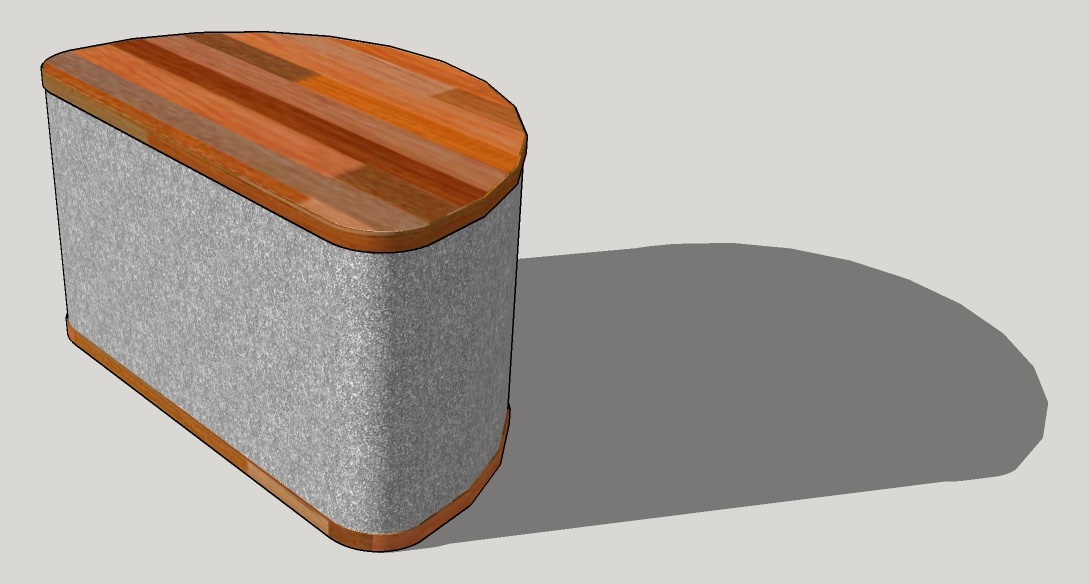

I'll make a model of my media console to see how it looks later.
/Anton
Played around a little in Sketchup. Outer dimensions are 50 x 28.2 x 30 cm and the waveguide mouth is thereby 40 x 25 cm.
I'll make a model of my media console to see how it looks later.
/Anton
Attachments
Nice looking design Onni. It's got a certain 1970's aesthetic and I mean that in a good sense. Very clean lines. A lot more WAF friendly than my rectangular box with a black baffle. I hope you can stuff all that into that little box. Those 8FE200's have a much larger bezel diameter than the smaller DC200's I used. I know I sure had a tough time fitting mine into a 46cm tall x 28cm wide x 33cm deep. This was using the Faital Pro LTH142 waveguide.
http://www.diyaudio.com/forums/multi-way/285030-bookshelf-multi-way-point-source-horn.html

http://www.diyaudio.com/forums/multi-way/285030-bookshelf-multi-way-point-source-horn.html
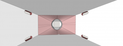
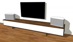
More sketchup
Here's how it would look on my media console (290 x 40 x 50 cm, W x H x D):

Showed this to my SO and she was surprisingly positive! I think I could make these in a way that she would let them in to our living room 🙂
I probably need to come up with some kind of feet to angle the mouth upward (towards ear-height while seated).
/Anton
Here's how it would look on my media console (290 x 40 x 50 cm, W x H x D):
Showed this to my SO and she was surprisingly positive! I think I could make these in a way that she would let them in to our living room 🙂
I probably need to come up with some kind of feet to angle the mouth upward (towards ear-height while seated).
/Anton
Attachments
- Home
- Loudspeakers
- Multi-Way
- Synergy attempt without compression driver