back to The Leach Amp
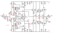
ok, here is my vision of the correction of this amplifier.
P.S. the initial current of each pair of output transistors is 110 mA.
Attachments
Last edited:
Not really, tech is tech sometimes it denies us an opinion, sometimes you want to think one way then the project expands your mind and you think another way, watch the video and see the phase lag oscillation🤦♂️
Each to his own then.
Thanks for sharing your ideas your recipe just like the original recipe are all valid.ok, here is my vision of the correction of this amplifier.
P.S. the initial current of each pair of output transistors is 110 mA.
The article is describing a known weakness of emitter followers: they are bidirectional. Some output gets fed back to the input.Bonsai said:See pages 19-23 in the link below. Although this mainly concerns itself with small signal buffers, the theory applies to power buffer stages as well, and especially in the case of EF2/3 and CFP.
https://worldradiohistory.com/UK/Wireless-World/00s/Electronics-World-2003-10-S-OCR.pdf
You, me, and Rotel all fixed the Leach amp in similar ways.Hennady Kovalsky said:ok, here is my vision of the correction of this amplifier.
Ed
Quasi complementary stages and CFP stages issues to note, the funky business around Q4. 390pF on R27 should take care of it
Who can make an educated guess at what was found to have caused the 8MHz oscillation, quite interesting find, and no its not the Zobel, video loading soon
On my own amp experiments, I suspect that mounting the outputs (and the drivers) on the same HS may cause (another) unwanted parasitic C, so I make changes in that regard....
Also, big C near the outputs may cause big currents to run on G and couple to other paths--> I decouple the G to HS.
But I am only a dilettante....
Best of wishes for your project!
M.
Also, big C near the outputs may cause big currents to run on G and couple to other paths--> I decouple the G to HS.
But I am only a dilettante....
Best of wishes for your project!
M.
Thanks @maxlorenz, good ideas there that actually work great for CFP, yes the grounds are decoupled.
The video is loading soon and its interesting what solutions do work
The video is loading soon and its interesting what solutions do work

An interesting article about buffers here https://worldradiohistory.com/UK/Wireless-World/00s/Electronics-World-2003-10-S-OCR.pdf
This amplifier is holographic and can create immense sound stage, sometimes requiring 10-20feet of listening space from speaker. It easily separates music that has space from music that has no space, pianos are life like, voices life like, flutes too real, cymbals believable , creates a live in studio experience. The prototype is biased at 130mA per C5200 WITH mje15032 used this instead of Darlington's, but you still need 100ohm base stopper resistors, using aluminum instead of servo.Dc offset 30mV
The 0.7c/w heat sinks per channel are not enough for heavy sessions, but sufficient for normal listening where they just stay warm
The proto type had the first break in phase within 72 hours (who knows what really happens), the next phase will be within a couple of days. Its so smooth when listening to hi res music am not yet tempted to replace the aluminums in the feedback path with the servo or film. The amplifier simply disappeared and what was left were the recordings. The foundation to a good musical experience is the amplifier, then the speaker and room and finally the source in that order. Am I missing the arc welding output stage of SYMEF, not really.
- Home
- Amplifiers
- Solid State
- Symphony Amplifier