Well boys...this is correct Nico Ras..you got the point... i have real strong
appreciation on you Nico.. you know that..also respect for you...also you know that.
Cal Weldon is rigth...thanks God (this is true) we have him here....or i would be punished in a couple of days.... you cannot say someone is retarded or something alike..it is forbiden..so..when you need to send some message, then you use their brain against themselves.
I cannot stand for some guys, this is the reality...they are very few guys, but i really think they are below the minimum line of human quality, despite can be excelent in their profession.... they have humiliated, in the past, Hugh Dean..and i cannot forgive such kind of thing...Hugh is a sweet person.. excelent researcher.... make specially good amplifiers...tuned for his speakers and personnal taste..others may feel need more bass, others may feel need more treble..depending the speaker you use.
I will build my amplifiers..that's what i gonna do...and never will go against Cal Weldon, he is fair, really fair..... i was waiting for him.
For sure, it is my strategy to provocate...sadly my provocations are not considered challenge.... challenge is considered when others goes provocating me..interesting.... something different on me..maybe thick skin or other thing.
I gave my message to the ones are clever....it is enougth to me...build amplifiers is much better than spend my time with some "specially clever guys"
regards all.....back to old Destroyer...destroying transistors.
Carlos
Last edited:
Just a simple question - is it OK if you push by an amplifying transistor stage, and pull just by current limited CCS? Is it better than to push and pull by the same principle?? Is it OK to have different limitation, different slewing of push and pull halves??
Intrinsically, the circuit will have a non symetrical transfert function,
which can be summarized as higher bandwith for the half wave that
is pulled by the amplifing device...
The drawback is, among others, a different slew rate for each signal polarity...
Symmetrical LTP and VAS works as two paralleled single ended ones. Slew rate is doubled and becomes symmetrical as both asymmetries add up and cancel. THD can be halved due to higher O/L gain.
Subjective impressions about amplifiers with less than 0.1% THD are b.s. for me, and will always be. Try to hear -60dB of any kind of noise when amplitude modulated by 0dB music. I find these crazy impresions a byproduct of spending too much time at home 😉 particularly when listening takes place in a non acoustically conditioned room with junk speakers.
I have repaired many of these fully symmetrical amplifiers, both car-audio, hi-fi and pro-audio. They all exhibited perfectly clean clipping behaviour with no traces of oscillation or sticking to the rails, and clean square wave response, two things that Carlos has not been yet able to achieve. The last oscilloscope videos that I saw demonstrated extremely bad clipping behaviour at least on one of his amplifiers. A funny way to circumvent that is to feel proud of imaginary achievements, but these seem ridiculous to most people except you. Always comparing yourself to less skilled people may also work for you but does not make sense for anybody else. Indulging in self pity does not work with oscilloscopes, they never lie.
Last edited:
Symmetrical LTP and VAS works as two paralleled single ended ones. Slew rate is doubled and becomes symmetrical as both asymmetries add up and cancel. THD can be halved due to higher O/L gain.
Subjective impressions about amplifiers with less than 0.1% THD are b.s. for me, and will always be. I find them a byproduct of spending too much time at home 😉 particularly when listening takes place in a non acoustically conditioned room with junk speakers.
Hello Eva
Are you saying that all amps with less than 0.1% THD do sound all same ?
I do not agree.
Btw, low quality loudspeakers could lower the overall sonic quality of a sound system, but a bad or dull sounding amp will kill all the sonic quality.
Bye
Gaetan
Last edited:
I'm saying that nobody can hear -60dB of noise modulated (and frequency related) by 0dB of music. The music is always 1000 times stronger than the noise. It's like feeling the difference between 1000 grams and 1001 grams of weight, or between 2000000 micropascals and 2002000 micropascals of acoustic pressure (that is 100dB music and 100dB music plus 40dB noise). It's something unrealistic, always backed by subjective claims.
And it's around 10 times lower THD than what I was able to hear in controlled 2nd and 3rd harmonic tests. So I'm assuming that the average human has 10 times better hearing than me (and I don't think I have bad hearing at all).
Another example. Try to tell a piece of wire 1000 milimeters long from another 1001 milimeters long just by sight, without measuring them or comparing one against the other.
Last edited:
I'm saying that nobody can hear -60dB of noise modulated (and frequency related) by 0dB of music. The music is always 1000 times stronger than the noise. It's like feeling the difference between 1000 grams and 1001 grams of weight,
You re assuming that the hand weighting a mass and the ear
listening a sound have both the same precision and relative
sensitivity , which is not true..
Think about the ten octaves we can ear, and the single octave
we can see...
Back to the sounds , listen to a pure sine , and then add a second
harmonic at very low level, you ll be surprised by the threshold
of its audibility...
I'm saying that nobody can hear -60dB of noise modulated (and frequency related) by 0dB of music. The music is always 1000 times stronger than the noise. It's like feeling the difference between 1000 grams and 1001 grams of weight, or between 2000000 micropascals and 2002000 micropascals of acoustic pressure (that is 100dB music and 100dB music plus 40dB noise). It's something unrealistic, always backed by subjective claims.
And it's around 10 times lower THD than what I was able to hear in controlled 2nd and 3rd harmonic tests. So I'm assuming that the average human has 10 times better hearing than me (and I don't think I have bad hearing at all).
Another example. Try to tell a piece of wire 1000 milimeters long from another 1001 milimeters long just by sight, without measuring them or comparing one against the other.
Hello Eva
Let say we talk now a bit about the brain and ears psycoacoustic.
Our brain/ears system can detect a time delay of few milisecond between our two ears, so we can have a stereo earing, but some of those psycoacoustic qualities of our brain/ears system rely on very low level sounds between 2khz and 6khz who are give us the sense of space and sound stage wen we ear sounds or musics.
So a bad amp with high frequencies harmonics in it's distortion spectrum will kill those low level sounds and we will lost the sense of space and sound stage in a musics listening.
The distortions number are not all, it's the distortions spectrum and which type of distortions who are important.
Bye
Gaetan
Last edited:
I agree that very high harmonics are much easier to hear because there is much less chance of these frequencies happening strong enough in the recording to mask the distortion products, but we are considering electronic systems with 4th and higher harmonics well below 0.1% (like 0.01%), thus usually below the noise floor, only 2nd and 3rd reach strong levels.
When THD is below 0.1% things such as output impedance become more important. The usual frequency-dependent output impedance figures can yield more than 0.2dB tonal unbalance due to frequency-dependent speaker impedance.
Note that 0.1% is more or less the same as 0.087dB
For example, in my three-way PA setup I can clearly hear differences in tweeter level as low as 0.2dB. I use a 24-bit digital crossover with controls in 0.1dB steps. We are very sensitive to tonal balance changes involving wide frequency bands, particularly at high SPL like 110dB-120dB where tone balance becomes critical, and changes as low as 0.5dB may turn pleasant into quite unpleasant listening. I routinely use a prototype speaker system capable of these SPL in my living room. In the past few years I have probably played with crossover filters and equalization and delays for a few thousand hours, so I think I have a good sense of what things we are sensitive to and what things we aren't.
Output impedance is seldom taken in consideration in class AB amplifiers. It's usually low in the range of .020 ohms up to 1Khz, rising smoothly to .2 ohms at 20khz. This changes with topology, transistor choice, frequency compensation, resistor values, etc. Many circuit changes result in unexpected changes in output impedance. People is doing that kind of changes on their circuits every day and claiming better or worse sound by means of unknown phenomena.
Consider the .02 ohm to 0.2 ohm rise in output impedance alone, with a 8 ohm load this already implies a 0.2dB tonal unbalance (from 1Khz to 10khz). Consider variable speaker impedance and tonal unbalance may worsen by another 0.2dB. This *can* be heard (and measured), but nobody talks about it. Is measuring these things too complex? 😀
I design my class D amplifiers to have as low output impedance as possible across the whole audio band. In my latest design a 2.8 ohm load makes less than 0.1dB difference in frequency response across the whole audio band, in comparison with no load. THD is below 0.1% up to insane power levels. In my opinion this is what results in neutral sound.
Last edited:
The .02 and 0.2 ohm figures are the result of a 400 LF damping factor falling to 40 at 10khz. These are good figures, since most circuits may have only 100 or 200 at LF falling to 10 or 20 at 10Khz, thus resulting in 0.8dB or 0.4dB of tonal unbalance.
Then factor in the typical output coil, 2uH gives an additional 0.1dB of tonal unbalance. 4uH gives 0.2dB. 8uH gives 0.4dB. Some circuits use a coil, others doesn't. The inductance of these coils is not well controlled, almost nobody measures them.
And all this being speaker dependent.
Then factor in the typical output coil, 2uH gives an additional 0.1dB of tonal unbalance. 4uH gives 0.2dB. 8uH gives 0.4dB. Some circuits use a coil, others doesn't. The inductance of these coils is not well controlled, almost nobody measures them.
And all this being speaker dependent.
Thanks for the infos, Eva , it s well explained..
Personaly, i dont like those LR filters at the output,
but to stay in the cautious side, i implement them,
but no more than 1uH//1R.
Personaly, i dont like those LR filters at the output,
but to stay in the cautious side, i implement them,
but no more than 1uH//1R.
Interesting that people seem to become shy when we stop splif rolling and we start to put numbers into the equations.
Anyway, output coils are a minor problem in comparison with the effects of working with an unknown and non-flat amplifier output impedance.
Anyway, output coils are a minor problem in comparison with the effects of working with an unknown and non-flat amplifier output impedance.
Last edited:
And it's around 10 times lower THD than what I was able to hear in controlled 2nd and 3rd harmonic tests.
Dear Ms. Eva,
please try also higher harmonics (in a controlled test).
I would add my results:
1% of 2nd H is at the edge of audibility
1% of 3rd H is distinguishable and audible
1% of 4th and higher H is horribly audible
0.1% of typical classB crossover distortion is easily audible.
Best regards,
.
Anyway, output coils are a minor problem in comparison with the effects of working with an unknown and non-flat amplifier output impedance.
Flat output impedance is not exactly possible , since
most, if not all , of the amplifiers have an open loop
frequency roll off that is well under 20khz , so the
output impedance , modeled by the negative feedback,
will start to rise symetrically to the gain roll off.
That said, a value of 1mR at 20KHZ can be achieved
with a low complexity circuit, and should be enough
in respect of the condition of audibility that you mentioned.
I disagree. Pole-pole-zero compensation with triple EF (and high Ft bipolars), or MOSFET output, allows to get flat open loop gain up to 10Khz or more (60dB of NFB or so), and then roll-off OL gain at more than 6dB/oct to get a not too high crossover frequency (where OL gain mets closed loop gain).
The 0.001 ohm output impedance figure at 20khz is unrealistic. That would be a damping factor of 8000 at 20khz. 400 across the whole audio band is a more realistic figure.
The 0.001 ohm output impedance figure at 20khz is unrealistic. That would be a damping factor of 8000 at 20khz. 400 across the whole audio band is a more realistic figure.
Very good 😀 but surely it does not come from the traditional 30-40 year old circuits discussed here. Also, it's simulation, it's easier to cheat.
A really simple test is to fed pink noise to the amplifier, do a real time FFT of the output with long time averaging, and compare frequency response with no load and with various loads.
My thresholds of perception of THD with pure sine waves are more or less the same as yours. This is the worst scenario because in real world almost every sound includes strong enough 2nd and 3rd harmonics to mask 0.1% (or 1%) more of the same stuff.
Class B distortion is a different thing because it produces harmonics too far from the input frequencies, and sometimes there is nothing to mask them. There are several methods for smoothing out zero current cross being discussed in other threads (error correction in various flavors, hyperbolic stuff, and even the ancient Visch paper, or whatever it is spelled), so I don't see it as an overlooked problem.
Last edited:
Member
Joined 2009
Paid Member
Dear Ms. Eva,
please try also higher harmonics (in a controlled test).
I would add my results:
1% of 2nd H is at the edge of audibility
1% of 3rd H is distinguishable and audible
1% of 4th and higher H is horribly audible
0.1% of typical classB crossover distortion is easily audible.
Best regards,
I'd be more interested to know your reactions to the higher order harmonics (i.e. 4th and above) are when there is already a reasonable level of 2nd and 3rd present. Or put it another way, it has been claimed that distortion harmonics are significantly less objectionable if they follow a clear decreasing trend from 2nd to 3rd and so on. Would the higher order harmonics be as audible in this case.
There are appears to be many ways to control the relative magnitude of 2nd and 3rd (the original topic here being symmetrical vs non-symmetrical amplifiers) but once it gets beyond the 3rd it seems things are much more difficult to control.
Last edited:
Know these are both a little off the symmetric amp subject. The point is high gain and wide bandwidth are both available today as they were many years ago other than the lack of "insightful" circuits. Very much agree with EVA! I have trouble achieving any output Z at 10kHz less than about 15mOhms. At 8 ohms damping would be about 500. Should measure this on the chip amp below at 10kHz.
Does symmetric mean symmetric slew rate or symmetric use of transistors? In the start it was devices. Symmetry could be added to the power LF351 and it would still be pretty much the same amp spec wise...
From post 49 in " 100W Ultimate Fidelity Amplifier "
I cannot say specific about ApexAudios amp but the "simplified" version more like a power LF351 has open loop: 85kHz -3dB bandwidth; gain of 95dB; THD 1%; symmetric slew rate; and output impedance of less than 1 ohm at 10kHz. That should leave plenty of room to find a compensation scheme which works. Would expect the ApexAudio amp to be very similar with possibly higher gain and possibly lower THD.
And from post 7 in " So just how "good" can a chip amp be ?"
My proprietary high gain 3886 chip amp competes welll for a stereo amp. Has 225dB gain at DC and 125dB gain at 10kHz. Vanishingly small distortion. Also features a second order DC servo loop and absolute stability with no output coil or RC network to make it safe or stable.
Last edited:
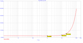
Also, it's simulation, it's easier to cheat.
I like to inject current into amplifier output terminals, and to display voltage vs. current then at different current amplitudes and frequencies. You can see crossover output impedance then. This one is for SymAsym amplifier at 10kHz. I do not remember V/div and A/div unfortunately 🙂
This is a typical non-symmetrical amplifier ... 😉
Attachments

- Status
- Not open for further replies.
- Home
- Amplifiers
- Solid State
- Symetrical schematics are alike plague in Brazil, do you like them?