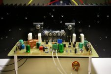
Sorry guys, I shouldn’t have published that last picture. The amp was almost ready for testing but not completely ready. I wouldn’t power it without first attaching all the transistors to the heat sink. As Joel said, that would result in thermal runway and flames. It has happened to me before in other projects and I learned my lesson. Also I never test an amp without a speaker protection circuit connected and one 10R 2W resistor in place of each fuse for current limiting. The trimmer is set to lowest quiescent current, fully turned clockwise. When testing I will connect a multimeter across one 0.22R resistor in milivolts scale to measure de voltage drop that should be 23mV. I also checked for electric contact between the transistors and the heat sink and found they are isolated.
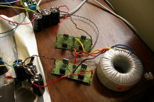
From the picture bellow you will notice I’m only using a pair of outputs. I will power the amp with 36V rails. I think it’s safe for now. In a final build I will use two sets of outputs even if I decide to keep the 36V. You also notice the coil is not very well made and that I’m using ceramic caps. I will replace the ceramic for silvered micas when I find the values.
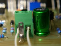
Thank you Harrison, I took out the 10R resistor and linked with a jumper. The input cap is a Nichicon Muse bipolar and the other puppy was a Panasonic FM polar cap. Took it out and replace with other Muse BP, 100uF 25V. Perhaps I should increase this value…
Tomorrow I’ll test the amp. I have only one channel build, I will not be able to comment about 3D soundstage, but I’m very curious to find out how this amp sounds! The expectation is placed very high! What attracted me to this amp was the beautiful harmonic spectrum and, I confess, the mystery involved in that secret (magic?) formula. Will it live to the expectation? I will find out tomorrow.
From the picture bellow you will notice I’m only using a pair of outputs. I will power the amp with 36V rails. I think it’s safe for now. In a final build I will use two sets of outputs even if I decide to keep the 36V. You also notice the coil is not very well made and that I’m using ceramic caps. I will replace the ceramic for silvered micas when I find the values.
Hi Paul kindly checkout this
Thank you Harrison, I took out the 10R resistor and linked with a jumper. The input cap is a Nichicon Muse bipolar and the other puppy was a Panasonic FM polar cap. Took it out and replace with other Muse BP, 100uF 25V. Perhaps I should increase this value…
Tomorrow I’ll test the amp. I have only one channel build, I will not be able to comment about 3D soundstage, but I’m very curious to find out how this amp sounds! The expectation is placed very high! What attracted me to this amp was the beautiful harmonic spectrum and, I confess, the mystery involved in that secret (magic?) formula. Will it live to the expectation? I will find out tomorrow.
Attachments


Listening test:
I have my pc soundcard directly connected with the amp. I also linked out the input cap.
The power supply is made of 3 x 6800uF no name capacitors bypassed by 100nF Wima MKP10 for each rail. Soft recovery diodes are used.
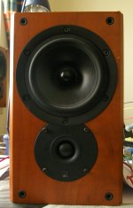
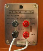
The speaker is a modest Kef Cresta 10 (previous series).
When connecting power the voltage across 0.22R rose up to 50mV and I disconnected the amp. The trimmer was full clockwise. I decided to put a 750R resistor in series with the 2k trimmer and that worked. Bias voltage is now 23mV stable.
So, how does it sound?
It’s a very enjoyable amplifier with a lively presentation. The mids are lust, particularly with female voices in a euphonic way that easily seduces. The bass is present with great control and is very well defined. The highs are rich and detailed (you can hear the little details and articulation of the voices) but are somewhat rough. This might very well be the psu’s fault or noise pickup by the wiring. It’s really the only thing I can complain about and I believe is not the amp’s fault. Other than this I think this amplifier has a beautiful presentation and deserves much more attention than what is getting here at Diyaudio. This is a very very good amplifier! Indeed the formula works. Now I will build the other channel and try to build a better psu.
I have my pc soundcard directly connected with the amp. I also linked out the input cap.
The power supply is made of 3 x 6800uF no name capacitors bypassed by 100nF Wima MKP10 for each rail. Soft recovery diodes are used.
The speaker is a modest Kef Cresta 10 (previous series).
When connecting power the voltage across 0.22R rose up to 50mV and I disconnected the amp. The trimmer was full clockwise. I decided to put a 750R resistor in series with the 2k trimmer and that worked. Bias voltage is now 23mV stable.
So, how does it sound?
It’s a very enjoyable amplifier with a lively presentation. The mids are lust, particularly with female voices in a euphonic way that easily seduces. The bass is present with great control and is very well defined. The highs are rich and detailed (you can hear the little details and articulation of the voices) but are somewhat rough. This might very well be the psu’s fault or noise pickup by the wiring. It’s really the only thing I can complain about and I believe is not the amp’s fault. Other than this I think this amplifier has a beautiful presentation and deserves much more attention than what is getting here at Diyaudio. This is a very very good amplifier! Indeed the formula works. Now I will build the other channel and try to build a better psu.
Attachments

Just inserted two paralleled Wima MKS2 4.7uF as input cap and the roughness I reported in my previous post is compeletly gone! 🙂 Most beautiful music I'm listening now! How can the ausence of input cap be the blame? I was though it was a power noise issue...
Hi Paul,
Thank you for
1. Committing your time and money to contribute to the state of the art
2. Taking a risk and getting rewarded in the process
3. Working soo fast
4. Experimenting
5. Sharing your first impressions with us
Kindly keep the thread up to date with your progress, post me a few photos of your board am interested about the bias...what are the surrounding components you used ?


Great job Drow, on the PCB.
kind regards,
Harrison.
Thank you for
1. Committing your time and money to contribute to the state of the art
2. Taking a risk and getting rewarded in the process
3. Working soo fast
4. Experimenting
5. Sharing your first impressions with us
Kindly keep the thread up to date with your progress, post me a few photos of your board am interested about the bias...what are the surrounding components you used ?
Great job Drow, on the PCB.
kind regards,
Harrison.
keep it up...
still there's more surprise to come ...after you finished the second amp...you will be amazed about this amp.what I really like about this amp. is the mid and bass.you are right the bass is more controlled and vocals is very very natural.
Look at previous thread I have given you part name of the input capacitor polypropylene at r.s. component.and also I have used mica all those pf value specially the 8.2pf. I have seen you have used metal spacer.
I have used copper tube and drilled the star gnd, of pcb.now my amp is grounded at chassis using copper tube, then I have connected the supply gnd between chassis and the copper tube .also twist the wiring of dc supply running through your amp.,do not include gnd. wire of power supply.
and most of all if you are using rca connector at your input make sure the gnd side of this connector is not touching the chassis.Gnd of this connector should go to board.
Gnd. of speaker also to be joined at the junction of copper tube and chassis.Do not connect it to the pcb.this is my set up and never fails me .the amp. will surely be quiet.
post more pics. Now they will now that this amp. is not made only through simulation.Harisson knew more about this amp. and surely he will not bring it here and put himself to shame and troubles.Many have said that it was more different when putting schematic into reality.output may surpass or not what is predicted through simulation.Have they forgotten what they said?
regards,
drowranger
p.s.
you work very fast and have seen your parts,most of them are standard or good quality.Now you can put the two output transistor.Congrats.
do you like this one.
Hi Harrison,
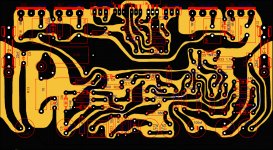
playing with my computer and come up with this one its not final but do you prefered this instead of straight line?Im just wondering if this kind of style can be done in computer(referring to my capability).thank you for the block diagram and this will serves as guidance through upcoming pcb.
thanks,
drowranger
Hi Harrison,
playing with my computer and come up with this one its not final but do you prefered this instead of straight line?Im just wondering if this kind of style can be done in computer(referring to my capability).thank you for the block diagram and this will serves as guidance through upcoming pcb.
thanks,
drowranger
Attachments
Hi Drow,
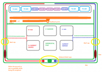
Creativity is highly encouraged 😉 . What I have in mind is to implement a ground plane that ensures that the board does not become an RF antenna.
I want us to merge your previous star ground system together with some RF protection techniques to come up with one fabulous board.
kind regards
Creativity is highly encouraged 😉
. What I have in mind is to implement a ground plane that ensures that the board does not become an RF antenna. I want us to merge your previous star ground system together with some RF protection techniques to come up with one fabulous board.
kind regards
I'll put star gnd.
will try in both version (straight and the jurrasic style😀).post this if anybody likes this style.feel free to comment😉
regards,
joel
will try in both version (straight and the jurrasic style😀).post this if anybody likes this style.feel free to comment😉
regards,
joel
Hi Joel and Harrison,
Joel, could you use Nico's sugestion and separate the VAS supply from the output transistors supply?
About the input cap: I will take a look at your polypropylen, Drow. Are you happy with it? I think the treble is very much dependant of the quality of this cap. But good 10uF cap might be very expensive. Harrison, is possible to rise the input impedance so a lower value, less expensive, better quality cap be used?
About the decoupling caps: I took out the Panasonic FC and now I'm using Panasonic FM. The FC's sound grany and FM's are much cleaner. Is the 33uF the optimal value for these caps or it's better to use higher values?
I prefer the straigh line. This round lines were used before computers were available and the boards were hand layouted.playing with my computer and come up with this one its not final but do you prefered this instead of straight line?
That's an excelent ideia!to come up with one fabulous board.
Joel, could you use Nico's sugestion and separate the VAS supply from the output transistors supply?About the input cap: I will take a look at your polypropylen, Drow. Are you happy with it? I think the treble is very much dependant of the quality of this cap. But good 10uF cap might be very expensive. Harrison, is possible to rise the input impedance so a lower value, less expensive, better quality cap be used?
About the decoupling caps: I took out the Panasonic FC and now I'm using Panasonic FM. The FC's sound grany and FM's are much cleaner. Is the 33uF the optimal value for these caps or it's better to use higher values?
First I want to optimize this one channel and after I'll build the second. Part selection is important, mainly that first cap. Any sugestions, Harrison?still there's more surprise to come ...after you finished the second amp...you will be amazed about this amp.what I really like about this amp. is the mid and bass.you are right the bass is more controlled and vocals is very very natural.
I'm blown away... again!
And I'm still using a single channel! 🙂 I know I'll be blown away again once I build the second!
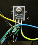
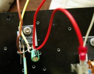
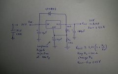
I just tried regulating the power supply with Linear Technology's LT1083 chip regulator and you guys must try this to!!! It's amazing - the midrange became so cleaner that it's unbeliveble!
The shortcoming of using this chip it's that it only regulates up to 35V, it's not possible to use 40V rails and up, and it requires two ground planes, each with it's own bridge rectifier. I built a quick power supply as in the pics atached.
Harrison, is it possible to regulate only the VAS and input stage? (as I believe the outputs don't (shuouldn't) need to be regulated). Is there a way to put such regulation circuit integrated into the amp's pcb?
What about the 33uF - should I rise them?
Please, guys, try listening to this amp with a regulated supply! You will be (again) blown away!
And I'm still using a single channel! 🙂 I know I'll be blown away again once I build the second!
I just tried regulating the power supply with Linear Technology's LT1083 chip regulator and you guys must try this to!!! It's amazing - the midrange became so cleaner that it's unbeliveble!
The shortcoming of using this chip it's that it only regulates up to 35V, it's not possible to use 40V rails and up, and it requires two ground planes, each with it's own bridge rectifier. I built a quick power supply as in the pics atached.
Harrison, is it possible to regulate only the VAS and input stage? (as I believe the outputs don't (shuouldn't) need to be regulated). Is there a way to put such regulation circuit integrated into the amp's pcb?
What about bass roll off?You can use a 4.7uF cap.
What about the 33uF - should I rise them?
Please, guys, try listening to this amp with a regulated supply! You will be (again) blown away!
Attachments
Last edited:
You don't have to thank me, Harrison. It is I who has to thank you for sharing this amazing amplifier! 🙂 From all my heart a big huge thank you!🙂Thank you for all your feedback
Hi Paul,
Such kind words .
.
Thanks again for contributing to the state of the art 😉 .
The amplifier was designed to blow you away even with an unregulated power supply😉
There are pros and cons of having the stages on separate supplies, but do experiment.
The regulated supply is helping the amplifiers power supply rejection, blowing you away again 😉
Adam was working on something related to the power supply rejection, also waiting to hear from him soon.
kind regards,
Harrison.
Such kind words
. Thanks again for contributing to the state of the art 😉 .
The amplifier was designed to blow you away even with an unregulated power supply😉
There are pros and cons of having the stages on separate supplies, but do experiment.
The regulated supply is helping the amplifiers power supply rejection, blowing you away again 😉
Adam was working on something related to the power supply rejection, also waiting to hear from him soon.
kind regards,
Harrison.
Will a regulated supply - like I did with this LT1083 - compromises transient response and dynamics? This chip is able to deliver 9A peak current, will this be enough for coping with the more demanding transients?😕
Hi Paul,
You could try paralleling them 😉
That thought crossed my mind! If the regulator can deliver big enough current then will I be safe from the shortcomings usually atributed to regulated supplies like poor transients, dynamics, etc?
Thanks.
- Home
- Amplifiers
- Solid State
- SYMEF amplifier