maybe tomorrow....maybe.
with those resistor I can still make the boards smaller and besides there are still some flaws on the latest,just minor like tracks on decoupling cap., not straight. while Im still making the boards just gather the parts.
regards,
joel
Thank you, drowranger, that would be great! 🙂
with those resistor I can still make the boards smaller and besides there are still some flaws on the latest,just minor like tracks on decoupling cap., not straight. while Im still making the boards just gather the parts.
regards,
joel
same as in my pcb.(previous)
ok.I'll put back the previous pot..because when I bought it on my supplier its pin configuration was in triangular form,then make remedy.(my first time to used that kind of pot).
regards,
joel
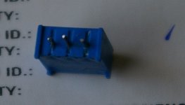
Joel, actually the trimmer is not triangular. The pins are in the same line. See the pic atached.
ok.I'll put back the previous pot..because when I bought it on my supplier its pin configuration was in triangular form,then make remedy.(my first time to used that kind of pot).
regards,
joel
There is an offset pin version of that VR.
Using a 4pad layout, allows either version to be inserted.
They both have horizontal pin pitch of 0.1" for a total width across the outer pins of 0.2".
The middle pin is either inline, or offset 0.1".
Using a 4pad layout, allows either version to be inserted.
They both have horizontal pin pitch of 0.1" for a total width across the outer pins of 0.2".
The middle pin is either inline, or offset 0.1".
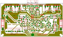
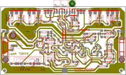
"QUOTE=drowranger;2907482 I made this last night and much smaller.if you can make a new layout much better because it suits your taste.
goodluck:😉
regards,
drowranger"
The two layouts (yours and Alex's) will have quite some difference in sound since your VAS transistors power supply is modulated by the power transistors which could cause a muddied or smeared sound. I would try and rearrange or separate the VAS supply from the output transistors supply.
Last edited:
Hi Nico,
Other than the packed muscle onboard the Alex version, both are topologically close.
Attached is a twist of what you maybe looking for 😉
However probably due to the formula, the amplifier is not likely to sound muddy, despite some inferred layout non optimizations. Lets say the formula could be several light years ahead of even the simulators math.
As Joel put it, its quiet and beats quite a few others out there 😉
kind regards,
Harrison.
Attachments
However probably due to the formula, the amplifier is not likely to sound muddy, despite some inferred layout non optimizations. Lets say the formula could be several light years ahead of even the simulators math.
This is really fanny.
This is really fanny.
Yes it is a bit funny, a magic formula that determines topology, component values, semi conductor choices, PCB layout, power supply determination.
Harrison, you have the idea regarding supply to the various sections. As it is with that particular layout every instant the power section passes current into the load a volt drop will develop across the VAS supply. The two amps of identical schematic will be audibly very different.
Whether a smeared sound is acceptable is as debatable as distortion, slew-rate, wide band, etc., it is not a science.
Surely this magic formula cannot have different sonic outcomes, then what is the point just allocate it a number. Let's say 7, if someone asks what the 7 means the answer is simple, you prefer it to any other number in the universe.
Last edited:
Hi Adam,
Sorry to keep you waiting for #180 the bottom mod. One or two proofs failed however, it may still be a good idea to construct it and listen to it and make a few measurements and a few mods.
kind regards,
Harrison.
Sorry to keep you waiting for #180 the bottom mod. One or two proofs failed however, it may still be a good idea to construct it and listen to it and make a few measurements and a few mods.
kind regards,
Harrison.
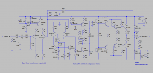
Hi Paul,
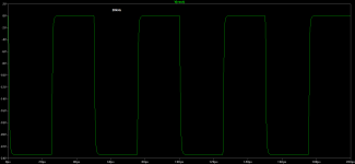
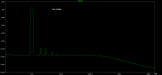
Here are a few sims of your proposed build.
Waiting excitedly at your experience, lets hope its love at first note even before warming up and breaking in
kind regards,
Harrison.
Here are a few sims of your proposed build.
Waiting excitedly at your experience, lets hope its love at first note even before warming up and breaking in
kind regards,
Harrison.
Attachments

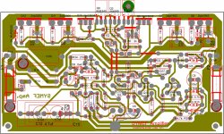
Hi drowranger,
That's a very nice pcb! 🙂
There's one little thing: the pin spacing for the 0.22R 5W resistors is 10 mm, it's a little small on the pcb. Otherwise, it's a beautiful pcb. Good work!
Many, many thanks drowranger! 🙂
That's a very nice pcb! 🙂
There's one little thing: the pin spacing for the 0.22R 5W resistors is 10 mm, it's a little small on the pcb. Otherwise, it's a beautiful pcb. Good work!
Many, many thanks drowranger! 🙂
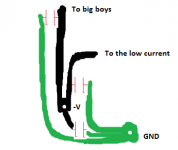
I'm not sure if I understand this... I must get a copper tube and solder it to the pcb star ground? Why can't I just use a wire?Just use a copper tube on pcb star gnd instead of wire
I don't think we can, Alex didn't published the copper side.and you can also use alex pcb
Hi Harrison,
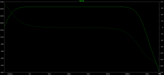
One thing I noticed is that the 2nd harmonic is dominant at 1kHz and the 3rd is dominant at 20kHz. Is this accidental or comes from the formula? High order harmonics are almost completely absent. 🙂
I did some simulations my self. It's a very promising harmonic distribution! 🙂Here are a few sims of your proposed build.
One thing I noticed is that the 2nd harmonic is dominant at 1kHz and the 3rd is dominant at 20kHz. Is this accidental or comes from the formula? High order harmonics are almost completely absent. 🙂

- Home
- Amplifiers
- Solid State
- SYMEF amplifier