anatech said:Hi roender,
Try a cascode for your fets to lock the voltage a little lower. That's been my plan all along.
What do you think about that idea Mike?
-Chris
Yes, the jfets should be cascoded, most amps cascode the input jfets. It also improves PSRR and makes the input less reactive. 🙂
Mike
MikeB said:
For better AC-balance at low freqs to the diffamp. Smaller c17 can improve bass... Bigger is not always better.
Mike
Mike, I'm not sure about that ...

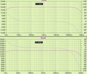
100uF vs 470uF AC analysis.

roender said:
Mike, I'm not sure about that ...
100uF vs 470uF AC analysis.
Standard symasym with jfets, positive PSRR, green = 100uF, red = 470uF.
Mike
Attachments
Here's the BOM for my PCB. I hope that I got all the parts, let me know if I goofed up anywhere. All the parts on the amplifier section are labled according to Mike's schematic. The PS is labled according to the schematic found in post #114. Also, label R23 near the bottom right mounting hole should be R12.
Al
Al
Attachments
AAK said:
So many amps, so little time....sigh...
I sure am watching with a lot of interest. Education by osmosis?...at least until I dig into it.
Any thoughts, ideas about others building it?
So many amps, so little time....sigh...
I sure am watching with a lot of interest. Education by osmosis?...at least until I dig into it.
I make some measurements between original symasym and my amplifier, modified version with k170 and more tail current.
Open loop gain:
1kHz -> original 27400, mod 13800
10kHz -> original 22900, mod 11100
20kHz -> original 16100, mod 7700
100Khz -> original 3600, mod 1700
Slewrate:
original 23V/us, mod 18V/us
PhaseShift at 1Wrms/8ohm 20KHz:
original -3.8grd, mod -3.1grd
I want to reduce close loop gain by 2 but I don't know if the amplifier will be stable.
I can't do that in spice, I don't know how. Can you help me Mike?
I would like to use current mirror and jfef cascode ion the input stage and also a cascoded JFet current source. To my expirence that improves clarity and texture.
I also think tha the secondary filter would be better if devided into two sections r-c wit 22 ohm and 2000 microfrarads.
It could also be a good idea to insert diodes in front of R14-15
best MiB
I also think tha the secondary filter would be better if devided into two sections r-c wit 22 ohm and 2000 microfrarads.
It could also be a good idea to insert diodes in front of R14-15
best MiB
Hi all,
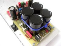
Well, good news. Everything works great with the new revised PCB. As you can see from the pic the output transistors no longer mount underneath the board. You'll need 4" of heatsink instead of three, but it's now DIY friendly. I'll post gerbers, and a revised BOM later today.
Al
Well, good news. Everything works great with the new revised PCB. As you can see from the pic the output transistors no longer mount underneath the board. You'll need 4" of heatsink instead of three, but it's now DIY friendly. I'll post gerbers, and a revised BOM later today.
Al
Attachments
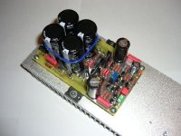
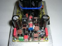
AAK said:Here's a pic of the amplifier section. The audio input is connected to the green terminal block.
Hi AAK, nice work! 🙂
Just one question, where are the 100uf for filtering supplyrails to the frontend gone ?
Mike
MikeB said:
Hi AAK, nice work! 🙂
Just one question, where are the 100uf for filtering supplyrails to the frontend gone ?
Mike
Sorry, my fault, you have used the 1000uF as filtering to the drivers + frontend...
Mike
Hi Mike,
There on the board. R31,C8,C10 filter the positive rail front end, and
R32,C9,C11 the negative. I'd guess the size of C8 and C9 through you off. There Nichicon KZ series 220uF/100V O.D 620 mils.
Al
There on the board. R31,C8,C10 filter the positive rail front end, and
R32,C9,C11 the negative. I'd guess the size of C8 and C9 through you off. There Nichicon KZ series 220uF/100V O.D 620 mils.
Al
- Status
- Not open for further replies.
- Home
- Amplifiers
- Solid State
- Symasym - the sequel