lgreen,
I used Mouser part no. 576-01000054N for my SymAsym boards and I picked this Littelfuse model because it is silver-plated. I believed that 576-01000054N is out of stock at Mouser but the part number 576-01000054H should have the same dimensions.
- Stanley
I used Mouser part no. 576-01000054N for my SymAsym boards and I picked this Littelfuse model because it is silver-plated. I believed that 576-01000054N is out of stock at Mouser but the part number 576-01000054H should have the same dimensions.
- Stanley
Hi Al,
I have a box of some generic red, green and yellow LEDs. Can I use these or should I stick to the particluar make you have specified in the BOM?
cheers
Aidan
I have a box of some generic red, green and yellow LEDs. Can I use these or should I stick to the particluar make you have specified in the BOM?
cheers
Aidan
Hi Aidan,
Do you know the LEDs forward voltage? If your not sure connect the LEDs cathode to about a 5k resistor and then a 12V supply and measure the voltage from the cathode to ground. If the voltage measures around 1.75V to 1.85V they should work fine. If not you may have to adjust the front end bias resistor R19 to compensate.
Regards,
Al
Boy it's been awfully quiet out here this week. Stanley (sng001) was the first out of the gate that I know of, how are the rest of you doing with the amp assembly?
Regards,
Al
Regards,
Al
Hi All
I just finished a low power version of my DTV Rev_1.3 PCB with the same amplifier circuit but with only a single OT pair and no on-board PS. The PCB measures only 2.5" (63.5mm) x 2.95"(75mm) which is perfect for a home theater amp using an external PS. The PCB provides provisions in the OT section to accept Lateral Mosfets for an all input/output fet operation.
Attached is a picture of the PCB and schematic. Since this is a low power version I dropped the rails to +/-36V and bypassed the differential/VAS cascodes. From my testing bypassing the VAS cascode increases 2HD resulting in a softer sweeter sounding amplifier.
Al
Attachments

During i'am working on amp layout. I drawn a PSU board to use MBR20_200CT i have on hand (25 unit). That will just nice for three psu board with double rectifier bridge.
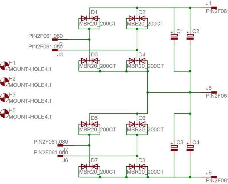
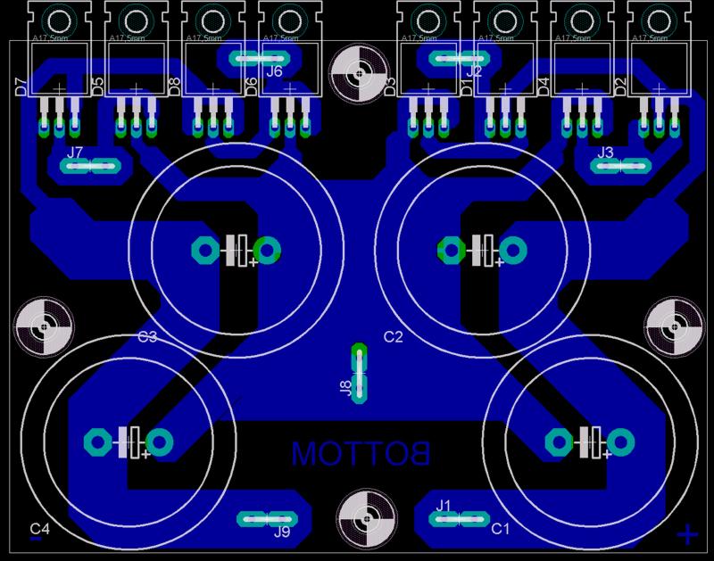
I will screw MBR on main heatsink, they will be solder under PCB board, same way as OUTPUT transistor on main amp board.
Marc
I will screw MBR on main heatsink, they will be solder under PCB board, same way as OUTPUT transistor on main amp board.
Marc
Last edited:
Your PS PCB looks real nice. How much capacitance per rail?
Al
Thanks. The board allows two 35mm caps per rails, so it depend on voltage rail, as lower it is higher is the cap capacitance for same diameter.
I have drawn a simillar board for heitgh MUR1520
Marc
Last edited:
BOM update, Fuse Clip part number change.
Hi All
I've attached a new BOM with a new Fuse Clip part number (576-01000054H) thanks to sng001. Igreen pointed out that the old part number had the wrong lead spacing. If you already bought them try bending the leads inward far enough to see if they reach the pads. Sorry about that.
Regards,
Al
Hi All
I've attached a new BOM with a new Fuse Clip part number (576-01000054H) thanks to sng001. Igreen pointed out that the old part number had the wrong lead spacing. If you already bought them try bending the leads inward far enough to see if they reach the pads. Sorry about that.
Regards,
Al
Attachments
Hi Al,
sorry for the slow progress here but finances are still recovering from Xmas. But I am getting there slowly. I'm also building one of Rod Elliot's 24db active 4 way crossovers - hence the need for more amps.
I have found out that VF for the LEDs that I've got is 2V for green and red and 2.1V for yellow. I measured a green one as you suggested and it was 1.9V - close. Do you think these will do?
Thanks for your help
cheers
Aidan
Hi Aidan,
Refer to post #36 regarding the LEDs.
I think they'll do but you may have to adjust R19. Initially leave R19 at 261 ohms and check the current across R23/R24. If the current is to high than increase R19 until you get it down between 1.65ma to 1.75ma.
Regards,
Al
Refer to post #36 regarding the LEDs.
I think they'll do but you may have to adjust R19. Initially leave R19 at 261 ohms and check the current across R23/R24. If the current is to high than increase R19 until you get it down between 1.65ma to 1.75ma.
Regards,
Al
Al,
The appearance of this edition fell into place for me. It will become part of a work in progress:
New speakers based upon Geddes/Parham/Zilch/augerpro. A 2-way using a hi-eff. 12" under a CD 90 x 50 horn. Bi-amped using your offering and the F-5. The bottom will be 4 X 10" subs. I expect to get ~117 dB if needed. 😉
Boards are in-hand. Parts are ordered. Aluminum has been cut and tapped. The fun continues. 😀
Last edited:
Hi Al,
I'm using a single output transistor for now on my amp with the supply rail voltage of +/-36Vdc. What would you recomend for the emitter bias voltage? Is it 25mv? On dual output transistor it's 55mv based on your contruction manual. Let me know.
Thanks,
Fred
I'm using a single output transistor for now on my amp with the supply rail voltage of +/-36Vdc. What would you recomend for the emitter bias voltage? Is it 25mv? On dual output transistor it's 55mv based on your contruction manual. Let me know.
Thanks,
Fred
Hi Fred,
Whether it's 25 or 55mv I see nearly no difference in THD at full power up to 20Khz. Either one is fine.
Regards,
Al
Whether it's 25 or 55mv I see nearly no difference in THD at full power up to 20Khz. Either one is fine.
Regards,
Al
- Status
- Not open for further replies.
- Home
- Amplifiers
- Solid State
- SymAsym - "The Sequel", AAK's PCB Builders Thread