Re: Alex do the things the way i like
DX is just teasing, looking for attention...ahahahahaaa
destroyer X said:
If Da Vinci decided to upgrade Monalisa...maybe would paint a moustache there..and all magic could disappear.
DX is just teasing, looking for attention...ahahahahaaa
By MJL - Don't take me so seriously.
Seriously , I never did .. AH hahahahaha !!! 🙂
OS

maybe would paint a moustache there..and all magic could disappear.
The "magic" ??? yeah.. 800 watts of brute force "sym" ... Ah Haha ha... I'm going power mad..

An externally hosted image should be here but it was not working when we last tested it.
Now the Mona lisa can say "mine is longer".. (goes with the mustache)
Seriously , this will most likely be the JULY amp . First of it's kind... (mutant sym - quasi NMOS 400). I know some hate FET's , but this seems the best route to harness the full power of a 1500VA trafo.
This presents a test load issue..
An externally hosted image should be here but it was not working when we last tested it.
😀 😀 hot bath or a cup of coffee , anyone ??
Who says we can't do what we want? I've seen threads where they propose a 500-1000 watt unit , and nothing gets built.
OS
ostripper said:
I've seen threads where they propose a 500-1000 watt unit , and nothing gets built.
OS
Not any of mine, seriously


🙂
MJL , we both know we are the exceptions.(contractors) The "master" (your guess) has said you, me and roender are the most real of the players. 😎
What are you driving with THAT !! ?? A 21" sub??
OS
What are you driving with THAT !! ?? A 21" sub??
OS
OS, the FET version looks like a brute machine. My opinion is that it will be very user friendly if Short-Circuit is added perhaps, with multiple slope features, so that it will not harm the sonics at normal to relatively high listening levels.
Do you think diodes on the collectors of the LTP will be a good idea for soft clipping?
Alex, you are doing a great job. Please don't get put off by those who are not willing to get past a certain degree of build complexity.
Do you think diodes on the collectors of the LTP will be a good idea for soft clipping?
Alex, you are doing a great job. Please don't get put off by those who are not willing to get past a certain degree of build complexity.
Hi MJL21193,
Hey! That is a really nice build there!
Will I ever see this in the flesh?
I believe you have cut the output section design right to the critical ideas. Simple and capable of very high current flows. No traces to lift off and resistors that actually have effective cooling. Really well done sir.
Hi ostripper,
I have to agree to some extend with your comments, but I would say there are other members that have been left out. MikeB for one (how could you forget him???) and there are many others, some in different forums, who actually do create working, build ready projects. The fact that you (and some others) take the time and expense to host these files yourself (and other reference information) shows me that the DIY spirit is strong, alive and well in your group.
All you people have my utmost respect and admiration for the efforts you put in. The amount everyone can learn from the collected works is truly amazing. Of course one can only learn if they stop talking long enough to take stuff in.
You have no worries about going unnoticed here. The only problems are the egos coming from arm chair critics. Possibly we should see something from those people when they pop up in the various threads? 😉 Let the membership decide who to listen to then. Actions in these cases speak much louder than the printed word.
Always remember, people who have done as you have are highly valued and respected, especially by the moderating team. Never worry about that.
Regards, Chris
Hi ostripper,
I started doing this in 2004 because I realized the same problems that you have. I even built a small EC PCB that I can tack in various designs.
My approach was similar to yours. I build voltage amp PCB's and power output PCB's separately, divided after the VAS. A natural dividing place. The direction I have been going lately is to enclose each section in it's own feedback loop. The voltage amp has one, and so the the output stage, there are exclusive of each other with minimal interaction. Only excessive loading from an output section can interfere with the voltage amp stage. A regulated supply for the voltage amp stage alone encourages total freedom from what is happening "out there".
I think you are ready to try this idea now, since you are developing that split anyway. Just think, once you have a stable voltage amp and/or output stage, there is much less to worry about and stability comes naturally. You now have freedom to experiment with more ideas since the building blocks are known quantities.
-Chris 😉
Excellent idea.I want to start on a standardized OPS so I can just "plug in" any modified LTP/VAS creation without having to redo the complete board.
I started doing this in 2004 because I realized the same problems that you have. I even built a small EC PCB that I can tack in various designs.
My approach was similar to yours. I build voltage amp PCB's and power output PCB's separately, divided after the VAS. A natural dividing place. The direction I have been going lately is to enclose each section in it's own feedback loop. The voltage amp has one, and so the the output stage, there are exclusive of each other with minimal interaction. Only excessive loading from an output section can interfere with the voltage amp stage. A regulated supply for the voltage amp stage alone encourages total freedom from what is happening "out there".
I think you are ready to try this idea now, since you are developing that split anyway. Just think, once you have a stable voltage amp and/or output stage, there is much less to worry about and stability comes naturally. You now have freedom to experiment with more ideas since the building blocks are known quantities.
-Chris 😉
MJL21193 said:
Why not? The more, the merrier! 😉
My version is ready, but I will not build the most powerful version, it is based on a version of 50W rms-8R that am working (that I will build )
I did the question because the title of the topic "the next generation (supersym)"
ostripper said:
I would not mind at all , In fact I would like to see it.. submit .asc and/or schema.. 🙂 is it triple.??

The triple output decreased distortion, recommend you try...
I removed the diodes and resistor of 22 to GND, good build powerful amplifiers with two power supply, resistor and the diodes are not needed with two power supply. of the resistor set bias I did not include, not made a difference in the simulation.
This resistor should not be before the degeneration?
Samuel Jayaraj said:My opinion is that it will be very user friendly if Short-Circuit is added perhaps, with multiple slope features, so that it will not harm the sonics at normal to relatively high listening levels.
In my version, short circuit protection begins work under 1 ohm load ouput, not affect the bass.
My version the minimum load is 4 ohms (360W rms). 2 ohms is not supported.
Samuel Jayaraj said:
Do you think diodes on the collectors of the LTP will be a good idea for soft clipping?
Not tried soft clipping, but it is not easy to implement, the reason is that this topology, working with two outputs of LTP
To measure Slew Rate, Rise Time and phase margin, you must remove the filter input and Zobel network.
-The response frequency in closed loop is 1.2MHz (without filter), 350Khz with filter.
Damping factor is 800 - 8R (with with inducer), 2000 without inducter (load capacitive 30 nF max, without inducter ).
asc file:
-The response frequency in closed loop is 1.2MHz (without filter), 350Khz with filter.
Damping factor is 800 - 8R (with with inducer), 2000 without inducter (load capacitive 30 nF max, without inducter ).
asc file:
Attachments
By anatech - You have no worries about going unnoticed here.
That is not my primary concern.. 😀 What I did do is promise a layout and PDF .I will release the main PCB artwork ,parts layout , schema , and BOM on one of my compiled PDF's tonight as promised. I was a little late as I had other obligations.
An externally hosted image should be here but it was not working when we last tested it.
This one is the "base" amp , later .. after I move (smoky mountains),
I will do the JFET version and the 2 board IRF "nuclear" release.(separate PDF's) Some have suggested that multiple versions of this amp are confusing , but so are different styles of automobiles. Each one I do has to work in my living room first before it is unleashed.
Raphael , you MUST add the directive ".include supersym-2.txt" ... also test the .asc by temporarily removing standard.BJT from your LT directory to confirm it's dependancy on your included model file (the .txt) 🙂
I could not get it to simulate... 🙁
OS
I find your work very interesting
Though it seems to me like a lot of copper and very few components
Im pretty sure the amount of copper needed could be much less with placing just a few components slightly different
Several copper lines seem to wiggle a bit much in places where just a bit of rearranging would straighthen the lines, and naturally make it smaller
Maybe also allow a few components to be mounted below board, if it makes layout much simpler
And few jumper wires also makes sense, if it makes layout simpler
Maybe also below board if needed or makes sense
Seems to me that it gives possitive results to try and have as many resistors as possible as "jumpers"
Regarding supply
It looks ok, but I prefer to have a bridge on each secondary, so that common ground is at the end of supply
One other point
Please make it possible to use seperate supply on input section, with slightly higher voltage
Looks like it already is readily possible, but Im not sure
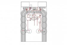
Below is a picture of how I like a supply, only this is a much smaller amp
I have removed all coupling film caps that are not needed in terms of stability, making layout even simpler
If anyone would insist on film coupling caps, it easy to mount them below board
ehhh, its not 100% finished yet
And yeah, I know, its a much simpler design
Though it seems to me like a lot of copper and very few components
Im pretty sure the amount of copper needed could be much less with placing just a few components slightly different
Several copper lines seem to wiggle a bit much in places where just a bit of rearranging would straighthen the lines, and naturally make it smaller
Maybe also allow a few components to be mounted below board, if it makes layout much simpler
And few jumper wires also makes sense, if it makes layout simpler
Maybe also below board if needed or makes sense
Seems to me that it gives possitive results to try and have as many resistors as possible as "jumpers"
Regarding supply
It looks ok, but I prefer to have a bridge on each secondary, so that common ground is at the end of supply
One other point
Please make it possible to use seperate supply on input section, with slightly higher voltage
Looks like it already is readily possible, but Im not sure
Below is a picture of how I like a supply, only this is a much smaller amp
I have removed all coupling film caps that are not needed in terms of stability, making layout even simpler
If anyone would insist on film coupling caps, it easy to mount them below board
ehhh, its not 100% finished yet
And yeah, I know, its a much simpler design
Attachments
ostripper said:..has said you, me and roender are the most real of the players. 😎
I'm sure there are others that build great stuff but don't show it - not as needful of attention as you, DX and I...😀
anatech said:Will I ever see this in the flesh?
Thanks Chris,
Hard pressed to find ANY free time lately. I did take today off, a break after 3 weeks steady - sat in the sun (hot enough for you today? 😀 ), drank a few and generally did nothing. Needed occasionally.
Back to the grind tomorrow, right through the weekend again. So much for the recession...😎
Not complaining 🙂
Many are trying or have downloaded the massive 90meg "supersym_pcb.bmp"..
I have put it in a PDF ( supersym_pcb_V-1.0.pdf ) in the same folder to facilitate an easy download for all the impatient ones.. 🙂
DO NOT DOWNLOAD the BMP'S !!! The PCB is trimmed and perfect (I hope)
OS
I have put it in a PDF ( supersym_pcb_V-1.0.pdf ) in the same folder to facilitate an easy download for all the impatient ones.. 🙂
DO NOT DOWNLOAD the BMP'S !!! The PCB is trimmed and perfect (I hope)
OS
- Home
- Amplifiers
- Solid State
- Symasym - the next generation (supersym)