Hi,
a Digital MultiMeter is ideal for measuring both output offset and hum/LF noise from the amp.
Short out the input to signal ground. (reduces noise but has no effect on offset).
Remove load from output. Retain output Zobel (on PCB).
Set DMM to 2000mVdc and measure output offset.
Reset to 200.0mVdc and measure again.
Set DMM to 2000mVac and measure output voltage.
Reset to 200.0mVac and measure again.
Good values are <2mVdc and <0.3mVac.
Acceptable values are <10mVdc and <0.7mVac.
I have found that removing the shorting link and leaving the input and output open circuit gives varying readings between 2mVac and 5mVac. Must be a lot of RF in the room!
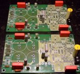
Is that input capacitor a polycarbonate? I liked them but can't find a cheap source any longer due to the non production of the carbonate film. They were cheap and fairly compact with good voltage capacity and sound quality.
a Digital MultiMeter is ideal for measuring both output offset and hum/LF noise from the amp.
Short out the input to signal ground. (reduces noise but has no effect on offset).
Remove load from output. Retain output Zobel (on PCB).
Set DMM to 2000mVdc and measure output offset.
Reset to 200.0mVdc and measure again.
Set DMM to 2000mVac and measure output voltage.
Reset to 200.0mVac and measure again.
Good values are <2mVdc and <0.3mVac.
Acceptable values are <10mVdc and <0.7mVac.
I have found that removing the shorting link and leaving the input and output open circuit gives varying readings between 2mVac and 5mVac. Must be a lot of RF in the room!
Is that input capacitor a polycarbonate? I liked them but can't find a cheap source any longer due to the non production of the carbonate film. They were cheap and fairly compact with good voltage capacity and sound quality.
Is that input capacitor a polycarbonate
The green ones are polycarbonate and available with not such a big value, so this is polyester imho.
The green ones are polycarbonate and available with not such a big value, so this is polyester imho.
Re: Is that input capacitor a polycarbonate
The green ones are probably polypropylene judging by their large size.
It's the silvery one tacked on to the underside of the PCB that I was interested in.
loek said:The green ones are polycarbonate and available with not such a big value, so this is polyester imho.
The green ones are probably polypropylene judging by their large size.
It's the silvery one tacked on to the underside of the PCB that I was interested in.
Hi,
C1 underside, i found in Farnell catalogue:
CAPACITOR, 4.7UF 100V
Capacitance:4.7µF; Tolerance, capacitance ±:±10%; Series:B32562; Voltage, rating:100V dc; Capacitor dielectric type😛olyester; Case style:Radial; Pitch, lead:15mm; Climatic category:55/100/56; Dept
Dc voltage at output swings from 4 to 6 mV with no load.
With the DMM on 200ma, on the output, i found 0.00 ? Doesn't move ?
Something wrong ?
JF
I hope that is not 200mA scale, you did mean 200mVac.jef9200 said:......Dc voltage at output swings from 4 to 6 mV with no load.
With the DMM on 200ma, on the output, i found 0.00 ? Doesn't move ?
4 to 6mV shows that lack of thermal coupling and/or less than perfect matching of the three pairs is giving a variable output offset.
But, if this covers a wide range of temperature then you will have no problem whatsoever.
I was pleased and very surprised at my excellent result, offset <=+0.9mVdc and never swinging more than 0.8mVdc. This is better than any previous amplifier I've built. Mike got this very right.
Hi,
I put the sound at higher level and made some mesures after, Vdc swings now between 3 and 5.
Sorry..for Vac, i made a mistake and mesure with 200ma scale.
I have only 2 scales for Vac ; 600V and 200V. ?
At higher level U5 and U6 begins to be hot, the two little heatsinks are necessary.
The problem with saturation seems to disapear...
I've read the mica condensators need some hours te be efficient.
The bias is set with 25mv across R28 and R27 (with 45vdc/rails). Is this a good value ?
It sounds good with more bass than my original symasym.
Thanks.
jef9200 said:B32562 Something wrong ?
Jeff,
if you want to stay low-budget you're much better off with a NOS KP/MKP motor run capacitor, MKT caps are not the best for signal coupling.
The Siemens B32562 series is the worst polyester capacitor choice, a polyester foil type performs even less compared to metallised foil.
The common economical thing 2 decades ago was placing a small polypropylene cap in parallel with the MKT.
Hi;
It is not a problem of "low-budget" . Some components are very difficult to find here.
Is Wima MKS4 a better choice for C1 ? I've found a seller not too far with this one:
CONDENSATEUR 4.7M 63V MKT 22.5MM MKS4
Thanks.
Jf
It is not a problem of "low-budget" . Some components are very difficult to find here.
Is Wima MKS4 a better choice for C1 ? I've found a seller not too far with this one:
CONDENSATEUR 4.7M 63V MKT 22.5MM MKS4
Thanks.
Jf
The green ones are probably polypropylene judging by their large size.
Hi Andrew, i also referred to the silver(siemens) cap on the right side....
Hi Andrew, i also referred to the silver(siemens) cap on the right side....
Bonjour à Louvain la neuve !jef9200 said:Hi;
It is not a problem of "low-budget" . Some components are very difficult to find here.
Is Wima MKS4 a better choice for C1 ? I've found a seller not too far with this one:
CONDENSATEUR 4.7M 63V MKT 22.5MM MKS4
Thanks.
Jf
You may also follow AAK suggestion :
WIMA 2.2uF/50V at Mouser part# 505-mks22.2/50/10
they are easier to find (Farnell, Radiospares, Selectronic, and of course Mouser ...) and should not make a lot of difference even if you listen to "Also sprach Zarathustra" and its organ low tones ...
Why so expensive ?
You can buy 50uF of that MKS2 junk for 5 Euro at the All Radio Parts shop in Tilburg, or order it from his Ebay store.
You can buy 50uF of that MKS2 junk for 5 Euro at the All Radio Parts shop in Tilburg, or order it from his Ebay store.
Hi Jacco,
Same as many of you can not get parts from North America that easily.
-Chris
We are at the mercy of our location for many European parts. They have us by the - (you know) - over here in North America. I have to order from the 'States. Normally from Digikey or Newark. Mouser is a lost cause for Canadians.Why so expensive ?
Same as many of you can not get parts from North America that easily.
-Chris
Al
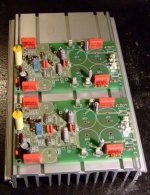
It looks like you are waiting for more than just a few items. Soldering components is quite relaxing. I never really gave the fumes part much thought. Will have to inhale some extra smoke and see how it goes.
What trannies are you using Al? Tad
It looks like you are waiting for more than just a few items. Soldering components is quite relaxing. I never really gave the fumes part much thought. Will have to inhale some extra smoke and see how it goes.
What trannies are you using Al? Tad
I've got all the semis, I just need to sit down and match them, and I've installed some more caps since that pic was taken. I'm waiting for electrolytics, rectifiers and resistors, all hopefully on the way.
For traffos, I'll probably be going with 30-0-30 to start, but I might bump up the rails on the five for the mids to 35-0-35, we shall see. I'm also undecided as to build two five way cases, or put them all actually in the speaker enclosures.
I'm tempted by a Class D solution for the bass end, that way all the amps would fit on some nice big heatsinks I have.
Hi Taj,
+-55V will require multiple parallel output pairs.
The standard 1pair with +-35Vdc can drive any 8ohm load and most 4ohm loads.
+-45Vdc will probably manage with 2pair output stage.
+-55Vdc may require 3pair for the same loading.
But low impedance loads draw high current and AAK's PCB has on board rectification and smoothing limiting the installed capacitance (25mm diam 4 off).
Higher voltage supplies would probably better suit 8ohm speakers and thus maintain good bass response.
- Home
- Amplifiers
- Solid State
- Symasym 5.3 "AAK model" builder's thread