Hi MBK,
Did you try pulling the sound card to see if your computer would boot?
I suspect the amp broke into oscillation. Often, I don't connect the output test ground. That can eliminate a lot of noise and other uglies.
-Chris
Did you try pulling the sound card to see if your computer would boot?
I suspect the amp broke into oscillation. Often, I don't connect the output test ground. That can eliminate a lot of noise and other uglies.
-Chris
Actually after the fact I realized I should have done just that, remove the presumably zapped soundcard. But I had one of these moments when I thought, I am tired, this one will go to the shop. Repairman says power is low internally and sometimes it starts booting, sometimes it doesn't, still trying to figure out where the issue is. Hope he thought of removing the card first, I told him what happened. Probably an open collector transistor in there, stealing current.
Before the "incident" I did one try where I removed the ground lead of the probe from the load end. RTA picture didn't change a bit though (ground is still connected through the input side). That's the trouble with the desktop, it is earthed and so is the amp PSU, any signal input has the potential to create a ground loop via earth. I don't use any tricks for earthing (resistor, diodes etc) because so far in my system I didn't run into audible troubles.
Before the "incident" I did one try where I removed the ground lead of the probe from the load end. RTA picture didn't change a bit though (ground is still connected through the input side). That's the trouble with the desktop, it is earthed and so is the amp PSU, any signal input has the potential to create a ground loop via earth. I don't use any tricks for earthing (resistor, diodes etc) because so far in my system I didn't run into audible troubles.
Hi MBK,
Most of the PC repair guys I've met don't troubleshoot well. I hope your part of the world is different than mine.
Since they haven't found the problem, even if it was only the card, they will "find" something else. That's the way it works over here anyway.
The only reason I know anything about computers, networking and surviving software is that the fellows I paid couldn't do it. I had to learn myself. 🙁 I'd rather have been able to pay them so I could get on with what I know how to do well.
-Chris
Thanks for the word of caution... I've seen quite horrible rip offs here too. This guy though owns his own shop and he's been around for a long time, his main business is building systems actually, so I have hope... Latest news is that the PC and even soundcard seem to work. It's the harddisk that was taken out (I suppose common mode transient, else I can't explain this). The disk being of course the only thing I really care for, with incomplete and infrequent backups etc. Serves me right. Anyway now he's sourcing for a harddisk controller.
On the amp news, progress too, not quite in the right direction though. I used the laptop again with the M-audio USB pre and w/o ground connection on the power side and laptop on batteries the signal is clean now. I must be in a very noisy environment btw, connecting open coax leads to the preamp gives quite a horrible signature (that is, nothing connected to the laptop but the cable itself, and battery operation). See attached pic.
You were right, my amps must be oscillating. Both channels I built have the same pattern, that's the good part because it means it's systemic to my parts selection. The bad part is that they both produce high levels of HD (-40 dB starting with 3rd, 2nd HD very low) and heat under some conditions. This occurs if the output is above 0.5-1V rms. One channel also produces a much higher DC offset when this happens (30 mA instead of 2 mA at idle). Low output or no load, or cold immediately after startup produces a very clean RTA and virtually zero DC offset.
The irony in all this is any changes I made to Al's BOM were to improve my chances for unconditional stability...
Here's the list of candidates and reason why I used a different part:
C14: 3.3 pF Mica, this was recommended by PMA when he did extensive testing using the same drivers and output devices (the Toshibas)
R32 and C9: I used Mike's latest recommendation of 47R and100 uF. Cutoff should be the same as Al's 22R and 220 uF though.
Zobel: I used Mike's values of 4R7 and 47 nF. I also used his output inductor of 12 windings AGW22 // 10R.
R1 R3 base stoppers output: used Mike's 1R2 instead of Al's 10R
R8 R9 base stoppers drivers: wanted to use Mike's 22R but forgot to order them so I used Al's 100R. Might this actually be the culprit?
R22, R24: used lower values to get higher bias.
C3 C4: used 220p as of PMA, again, instead of 330p as of Al
In terms of brand/type I either used Al's exact parts off Digikey, or get equivalents locally. One significant exception is C2, 3, 4, 7 (small pF range). I used good quality ceramics here.
And, or course, I did use offboard rectification, using Al's recommendation of a 0R2 resistor in series with the rectified DC supply. The XF is a 225VA 25V with a 25A standard bridge and 0.1 uF 200V transient suppressors. Earth connects to power ground at the junction of bridge to center tap.
When I matched the transistors I found that all of them had h(fe), in the 100-120 range. That's both the small signal 2N types, NPN and PNP, and the 2SA/SC ouput transistors. Nothing unusual here and corresponds to datasheets.
All else right off Al's BOM. Bias is 75 mA, heat sinks hand warm and low DC offset at idle.
Sorry to throw this laundry list up here, but I don't have enough experience in discrete circuits to know what actually may be significant here...
Attachments
Hi MBK,
A real oscilloscope would be very handy right now.
100R base stoppers? Wow, that's high!! Try to get close to one or the other BOM. I used the 5.3 release to build mine. Pavel or Mike may have some better insights on this.
C14 can be critical, zobels are normally "in the ballpark" type things. C3,4 may make a difference.
Your choice of ceramic may just make the amp sound worse in character. This depends on a lot. Ceramics will not make these amps oscillate. So get your resistors and caps closer to what they should be and check again.
-Chris
Hi MBK,
Here's my attempt to answer your listed question. Hope it helps.
C14: 3.3 pF Mica, this was recommended by PMA when he did extensive testing using the same drivers and output devices (the Toshibas)
-- This value should be fine. But if it's causing the oscillation removing it should stop it.
R32 and C9: I used Mike's latest recommendation of 47R and 100 uF. Cutoff should be the same as Al's 22R and 220 uF though.
-- Should be fine.
Zobel: I used Mike's values of 4R7 and 47 nF. I also used his output inductor of 12 windings AGW22 // 10R.
-- Should be fine.
R1 R3 base stoppers output: used Mike's 1R2 instead of Al's 10R
-- Use 10 ohms instead. Don't think it's causing the amp to oscillate, but worth a try.
R8 R9 base stoppers drivers: wanted to use Mike's 22R but forgot to order them so I used Al's 100R. Might this actually be the culprit?
-- Should be fine, keep them at 100 ohms. You'll find the many amps that use these drivers including the AKSA use 100 ohm base stoppers.
R22, R24: used lower values to get higher bias.
-- No problem here.
C3 C4: used 220p as of PMA, again, instead of 330p as of Al
-- Should be fine.
In terms of brand/type I either used Al's exact parts off Digikey, or get equivalents locally. One significant exception is C2, 3, 4, 7 (small pF range). I used good quality ceramics here.
-- Should be Ok, but I'd use micas.
And, or course, I did use off board rectification, using Al's recommendation of a 0R2 resistor in series with the rectified DC supply. The XF is a 225VA 25V with a 25A standard bridge and 0.1 uF 200V transient suppressors. Earth connects to power ground at the junction of bridge to center tap.
-- I'd disconnect earth from power ground. Connect it to the chassis only. Could be causing a ground loop. Also, if you happen to have two amps connected to a single off board PS while testing, try one instead to see what happens
When I matched the transistors I found that all of them had h(fe), in the 100-120 range. That's both the small signal 2N types, NPN and PNP, and the 2SA/SC output transistors. Nothing unusual here and corresponds to data sheets.
-- Should be fine.
All else right off Al's BOM. Bias is 75 mA, heat sinks hand warm and low DC offset at idle.
--I'm wondering if the oscillation is a result of something funny going on when the sound card is connected to the amp. Try checking the voltage across R27,R28 with the input grounded, then open, and then with the sound card connected but with no input signal. Do you see any significant difference in voltage?
Al
Hi Chris, Al,
thanks for the ample input. So I started experimenting.
The soundcard definitely does something. To specify what I am doing: the best way I found connecting it is, soundcard unbalanced out to amp, and probe lead to a 4.7k / 120R voltage divider across a 6R power resistor load, for -32 dB attenuation. I only connect the signal probe lead, and it goes to one lead of a balanced input on the soundcard. The Mobile Pre I am using unfortunately does not have an unbalanced line input, except for a microphone input. Using this one creates the worst RTA picture, with plenty of noise even without signal, the mic pre must not be very good and is too sensitive anyway. The other lead is "grounded" which is actually not true, because the sleeve of the balanced phono jack inout of the soundcard is actually *not* grounded, and connecting probe ground to it leads to immediat demise of the amp's 5A fuse. In any case, connecting the amp this way gets me a reasonable noise picture if no signal is applied.
Soundcard is USB powered by a laptop on batteries, so the earth should not cause a ground loop. If i power the laptop by line cord, then yes, it's absolutely awful.
So the results so far:
- amp input open, shorted, with open lead, powered off preamp with or without probe, all do nothing to the bias (about 75 mA).
- amp input connected to powered-on soundcard , no signal: bias (DC, via DMM) shoots up to 0.5 A. Connecting the probe lead as well and the bias increases another 50 mA.
Experiments so far:
- input goes 4 windings through a ferrite bead for added input filtering: no effect whatsoever. Might be too little though.
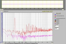
- adding 10p to the 3.3p C14 by tack soldering a cap: interestingly, bias must be readjusted quite a bit (it went down 50% for the same previous r24 setting). With the added cap, connecting the preamp now does nothing to the bias, it is now stable whatever I do. But when applying signal, the spray of all-odd harmonics is still there (see pic for 4V rms output into 6 Ohms). I checked loopback on the soundcard and it can easily take this input voltage w/o distortions, since it is receiving it via the -32 dB divider.
What's strange is that I am getting all odd harmonics. Which one of the symmetrical stages is saturated? ...
I guess the next easiest thing will be to double up the driver base stoppers with 30R to give 100R//30R = ca 23R, as in Mike's BOM, that's easier than pulling the output base stoppers to increase their value to Al's 10R.
thanks for the ample input. So I started experimenting.
The soundcard definitely does something. To specify what I am doing: the best way I found connecting it is, soundcard unbalanced out to amp, and probe lead to a 4.7k / 120R voltage divider across a 6R power resistor load, for -32 dB attenuation. I only connect the signal probe lead, and it goes to one lead of a balanced input on the soundcard. The Mobile Pre I am using unfortunately does not have an unbalanced line input, except for a microphone input. Using this one creates the worst RTA picture, with plenty of noise even without signal, the mic pre must not be very good and is too sensitive anyway. The other lead is "grounded" which is actually not true, because the sleeve of the balanced phono jack inout of the soundcard is actually *not* grounded, and connecting probe ground to it leads to immediat demise of the amp's 5A fuse. In any case, connecting the amp this way gets me a reasonable noise picture if no signal is applied.
Soundcard is USB powered by a laptop on batteries, so the earth should not cause a ground loop. If i power the laptop by line cord, then yes, it's absolutely awful.
So the results so far:
- amp input open, shorted, with open lead, powered off preamp with or without probe, all do nothing to the bias (about 75 mA).
- amp input connected to powered-on soundcard , no signal: bias (DC, via DMM) shoots up to 0.5 A. Connecting the probe lead as well and the bias increases another 50 mA.
Experiments so far:
- input goes 4 windings through a ferrite bead for added input filtering: no effect whatsoever. Might be too little though.
- adding 10p to the 3.3p C14 by tack soldering a cap: interestingly, bias must be readjusted quite a bit (it went down 50% for the same previous r24 setting). With the added cap, connecting the preamp now does nothing to the bias, it is now stable whatever I do. But when applying signal, the spray of all-odd harmonics is still there (see pic for 4V rms output into 6 Ohms). I checked loopback on the soundcard and it can easily take this input voltage w/o distortions, since it is receiving it via the -32 dB divider.
What's strange is that I am getting all odd harmonics. Which one of the symmetrical stages is saturated? ...
I guess the next easiest thing will be to double up the driver base stoppers with 30R to give 100R//30R = ca 23R, as in Mike's BOM, that's easier than pulling the output base stoppers to increase their value to Al's 10R.
Attachments

Aw-kay... Next mod: driver base stoppers = 22R, C14 is back to 3.3p not to mix up the mods. Now all base resistors are as in Mike's BOM.
Result: connecting the soundcard now does not upset the bias anymore, same effect that I had when modifying C14. But the distortion spectrum worsened to 1.5% at 4V RMS, and now, for a first, we also have very high even order distortion, the works!
I also noticed (can be seen on the graph) that using the touchpad on the laptop results in broadband noise bursts in the 5-12k area, some remnants can be seen on the graph. Sigh.
I am more and more clueless. Maybe it is the soundcard, but when I tried double checking with the desktop I fried it. Before it went I had a chance to see the distortion spectrum and it was just the same as on the USB laptop card.
Attachments
One more question mark: for Al's PCB R26 had to be increased to 150 Ohms, to prevent thermal runaway of the drivers. But C6 which bypasses it, remained at 100nF as it was in Mike's original BOM, which had R26 at 33R. Cutoff of 150R//100n is 10kHz and 33R//100n gives 50kHz. Any thoughts?
I also re-read PMA's page on using Mike's BOM with 2SC5200/2SA1943, he found severe 6MHz oscillations at 55 mA bias and they only went away reliably when reducing it to 10 mA. He eventually cured the problem for any value of bias by reducing C14 to 3.3p, that's why I did the same. Funny thing is I notice when starting from cold and observing bias climb from about 20 to 75 mA, the problems really are initially absent and come on as the bias climbs, first in bursts, then permanently. Maybe my specific choice of brand in c19 and c20 interferes with c14 (RLC combo's resonance?). Tough to reduce c14 even further, with parasitics all bets are off even at 3.3p as it stands...
I also re-read PMA's page on using Mike's BOM with 2SC5200/2SA1943, he found severe 6MHz oscillations at 55 mA bias and they only went away reliably when reducing it to 10 mA. He eventually cured the problem for any value of bias by reducing C14 to 3.3p, that's why I did the same. Funny thing is I notice when starting from cold and observing bias climb from about 20 to 75 mA, the problems really are initially absent and come on as the bias climbs, first in bursts, then permanently. Maybe my specific choice of brand in c19 and c20 interferes with c14 (RLC combo's resonance?). Tough to reduce c14 even further, with parasitics all bets are off even at 3.3p as it stands...
Hmm, another possible source of error are the emitter resistors, wirewound, as specified in Al's BOM, but not that precise type because they were from Mouser adding anothe r$50 or so in shipping. I actually tried to source metal oxide to be on the safe side inductance wise but couldn't find any locally. So I am using this Vishay wirewound type:
0.2R Vishay power resistor
Looks like I'll end up pulling every single part out of the pcb and mix and match at random guess in a 256 item combinatorial matrix.
0.2R Vishay power resistor
Looks like I'll end up pulling every single part out of the pcb and mix and match at random guess in a 256 item combinatorial matrix.
Just babbling on, so that my case may serve as a warning to others 🙄
- tried replacing R1 and R3 by AAK's 10R instead of Mike's 1.2R, this on the channel that has R8 and R9 at AAK's 100R. C14 and C3 C4 still at PMA's 3.3p and 220 p, respectively. No improvement. Bias still jumps 10-fold at connection to soundcard and HD at -40dB or so.
- on the channel that has all values like Mike's and PMA's recommendations and which w/o furhter mods also doesn't work at all (c14 = 3.3p, C3, 4 = 220p, R8,9 = 22R, R1, 3 = 1.2R): added heavy handed input filter outboard via 1k series 1n shunt (160kHz lowpass). This gave again a stable bias upon soundcard connection an also really improved the HD situation - but still not clean enough, now HD at -60dB.
It is entirely possible that the soundcard produces a parasitic carrier frequency that is too close to the audio band to be taken out completely by the input filters and yet is invisible to the soundcard's DAC, say 200kHz or so; at say 0.3V or 0.5 V rms the amp would amplify such a parasitic "bona fide" and basically clip, or close to. That woudn't even be oscillation, just unfortunate out of band amplification. Unfortunately I can't test this w/o a scope.
So, next best, the next try will be to use a clean external signal source (test CD from standalone player) and use soundcard for measurement only. In any case though with any and all mods tried so far the amp is at best marginally stable, since some mods have at least produced significant changes, so it can't just be the soundcard alone.
There are plenty of wireless routers and handphone, cable TV, aerial TV etc around here as well so the environment is noisy for sure, but hey, that's where it's supposed to operate in eventually...
MBK, have you tried using completely my BOM ?
Means: c14=10p, c3/4=330p, r13=2k, c2=100p.
Have you verified r2=10ohm?
Did you change r29/30 for lower gain? (r29=22k,r30=500)
Many have built Symasym, you are the first with such big problems. The fact that bias jumps 10-fold by connecting a source is a sure indicator for heavy oscillation. Have you missed c7=100p?
Sadly, i am not completely familiar with the AAK version.
Have you already tried disconnecting earth from ground? In my experience earthing is evil. You can earth your chassis, nothing else, avoid any connection from earth to ground.
Mike
MBK:
your problems sure sound strange considering the number of folks who have built this amp without issue.
sure you're not using any fake semi's?
mlloyd1
your problems sure sound strange considering the number of folks who have built this amp without issue.
sure you're not using any fake semi's?
mlloyd1
MikeB said:MBK, have you tried using completely my BOM ?
Means: c14=10p, c3/4=330p, r13=2k, c2=100p.
Have you verified r2=10ohm?
Did you change r29/30 for lower gain? (r29=22k,r30=500)
Many have built Symasym, you are the first with such big problems. The fact that bias jumps 10-fold by connecting a source is a sure indicator for heavy oscillation. Have you missed c7=100p?
Sadly, i am not completely familiar with the AAK version.
Have you already tried disconnecting earth from ground? In my experience earthing is evil. You can earth your chassis, nothing else, avoid any connection from earth to ground.
Mike
I don't know if this is a general problem, but my limited experience supports Mike's comments. Using the amps with a regular tube preamp, I had no problems. But, when I started multiamping with a DEQX, I had noise problems related to grounding. I suspect that this is because there were to many earth connections - 8 channels of amplification, in my case.. I could eliminate most of the problems by arranging the mains plugs in kind of a star pattern. I later found that it helped to lift the circuit connection to ground. In two symasyms, I used antiparallel diodes. In the others, I just disconnected the circuit/earth connection. Chassis remained earthed, as Mike suggests.
BTW, I didn't have these kind of problems with my tube amps. I wonder if ss amps are more sensitive to this issue, because the open loop gain is much higher as is feedback. So this may be a place where ground signals are amplified and become a problem.
Sheldon
Not my finest hour.
I finally got my 2 X 33 Plitrons, and have spent the last two days completing the boards and wiring everything together. I've been really careful, metering each component before installing it and checking the boards twice after assembly. So, I am really disappointed to report that I am unable to correctly bias either channel. One channel will bias no higher than 15mv (measured across R27 and R28), and the other will bias no lower than 26mv, even though all four rails are running within a 50.3 to 50.5 volt range.
The only component value different from that on Al's BOM is a 7pF cap at C14, and most components are the same as those on the BOM, except for several Shinkoh resistors and BlackGate caps.
Anyone have any ideas, or suggestions for a process to find out what's wrong?
Thanks.
Considering-checking-mains-voltage-with-my-tongue in NC.
Hi Mike,
thanks for stopping by.
First off, AAK (Al)'s board has a few differences to yours:
- no r2, Agnd connects to Ignd at speaker return
- no provision for input degeneration
- no output inductor on-board, but I added it right at the speaker connector inline in the cable
Getting there retrofitting... I'll soon be at the point where one channel is completely Mike and one completely AAK, sadly I meant well initially and selectively mixed the BOMs to make sure I use the latest recommendations. Too much thinking does no good.
- I tried adding 10p to the 3.3p of C14, but at this point c3/4 were still 220p and r8/9 at 100r. Will add 100p to c3/4 and replace c14 completely with 10p (only have ceramic at hand)
- r29/30 always were at your 499/22k values
- r13 and c2 were always your values
- no r2, due to PCB
- c7 always was well in place though I used a good ceramic here
Earth: well. Many have commented now on this. Like Sheldon I use a star earth on my existing active x-o and 6 channels of chip amps, seems to give me no troubles, that's why I wasn't too concerned. Plus, the laptop is on batteries when testing - no earth loops are possible, internal gound loops maybe yes.
But more importantly - why I haven't tried disconnecting Earth for testing - is this fear: I already fried my main PC testing Symasym... If I now let the 225 VA toroid float and connect it to the floating laptop/USB card , am I going to get the next common mode transient that sends my laptop do kingdom come as well? Thinking it through it's irrational but I don't trust rational anymore at this point.
Semis are all from Digikey and measured very well / consistently during matching.
Colescuttle: sorry to hear. Odd that the channels behave differently. Don't quite have an idea here, except, check your building.
thanks for stopping by.
First off, AAK (Al)'s board has a few differences to yours:
- no r2, Agnd connects to Ignd at speaker return
- no provision for input degeneration
- no output inductor on-board, but I added it right at the speaker connector inline in the cable
MikeB said:MBK, have you tried using completely my BOM ?
Means: c14=10p, c3/4=330p, r13=2k, c2=100p.
Have you verified r2=10ohm?
Did you change r29/30 for lower gain? (r29=22k,r30=500)
Have you missed c7=100p?
Sadly, i am not completely familiar with the AAK version.
Have you already tried disconnecting earth from ground? In my experience earthing is evil. You can earth your chassis, nothing else, avoid any connection from earth to ground.
Mike
Getting there retrofitting... I'll soon be at the point where one channel is completely Mike and one completely AAK, sadly I meant well initially and selectively mixed the BOMs to make sure I use the latest recommendations. Too much thinking does no good.
- I tried adding 10p to the 3.3p of C14, but at this point c3/4 were still 220p and r8/9 at 100r. Will add 100p to c3/4 and replace c14 completely with 10p (only have ceramic at hand)
- r29/30 always were at your 499/22k values
- r13 and c2 were always your values
- no r2, due to PCB
- c7 always was well in place though I used a good ceramic here
Earth: well. Many have commented now on this. Like Sheldon I use a star earth on my existing active x-o and 6 channels of chip amps, seems to give me no troubles, that's why I wasn't too concerned. Plus, the laptop is on batteries when testing - no earth loops are possible, internal gound loops maybe yes.
But more importantly - why I haven't tried disconnecting Earth for testing - is this fear: I already fried my main PC testing Symasym... If I now let the 225 VA toroid float and connect it to the floating laptop/USB card , am I going to get the next common mode transient that sends my laptop do kingdom come as well? Thinking it through it's irrational but I don't trust rational anymore at this point.
Semis are all from Digikey and measured very well / consistently during matching.
Colescuttle: sorry to hear. Odd that the channels behave differently. Don't quite have an idea here, except, check your building.
Hi Colescuttle,
If your using my BOM you should be able to adjust the voltage across R27,R28 from near zero to about 40mv. You can increase the bias further by dropping R24 to about 220 ohms, this will put the vbe multiplier near equivalent to MikeB's design. What's the DC offset on the output look like? Make sure you wipe off all the solder paste from the board, could be the problem.
MBK, you can use MikeB's BOM except since on my PCB the drivers are not mounted to the heatsink keep R26 at 150 to prevent the drivers from entering thermal runaway.
Al
MBK said:But more importantly - why I haven't tried disconnecting Earth for testing - is this fear: I already fried my main PC testing Symasym... If I now let the 225 VA toroid float and connect it to the floating laptop/USB card , am I going to get the next common mode transient that sends my laptop do kingdom come as well? Thinking it through it's irrational but I don't trust rational anymore at this point.
One safe method is to use a pair of anti parallel diodes to lift the ground from earth - high impedance at low potential, but low impedance at one diode drop or above. If you are concerned about major faults, use diodes or big enough to take out fuses before the diode fries. A bridge works fine for this - AC inputs tied together, DC inputs tied together, one to ground, one to earth.
Sheldon
Re: Not my finest hour.
Take a look at this post, which give the voltages at various points in the circuit: http://www.diyaudio.com/forums/showthread.php?postid=683533#post683533
Also take a look at the post that follows it, which gives current values (also posted on Mike's page).
Check them until you find something amiss, as surely something must be.
Sheldon
Colescuttle said:I finally got my 2 X 33 Plitrons, and have spent the last two days completing the boards and wiring everything together. I've been really careful, metering each component before installing it and checking the boards twice after assembly. So, I am really disappointed to report that I am unable to correctly bias either channel. One channel will bias no higher than 15mv (measured across R27 and R28), and the other will bias no lower than 26mv, even though all four rails are running within a 50.3 to 50.5 volt range.
The only component value different from that on Al's BOM is a 7pF cap at C14, and most components are the same as those on the BOM, except for several Shinkoh resistors and BlackGate caps.
Anyone have any ideas, or suggestions for a process to find out what's wrong?
Thanks.
Considering-checking-mains-voltage-with-my-tongue in NC.
Take a look at this post, which give the voltages at various points in the circuit: http://www.diyaudio.com/forums/showthread.php?postid=683533#post683533
Also take a look at the post that follows it, which gives current values (also posted on Mike's page).
Check them until you find something amiss, as surely something must be.
Sheldon
OK, latest test was using Mike's standard values for everything except:
- R26 at 150R
- R31/32 at 47R as of Mike's latest recommendation
Initially I saw again a jump in bias upon connecting preamp, then realized I left the wireless card on. Switchedd it off, bias stable, HD still not quite OK at lower power (-60dB) and definitely unacceptable at higher power into 6R, again -40 dB HD at something like 7VRMS into 6R.
What's left?
- Earth. Well, I'll try the diodes for testing. It would bug me a lot though if Symasym can't take earth. I did try diode isolation and 10R // small cap on my system at some point but got *more* hum and noise issues. Then I earthed everything, but carefully so, always just one earth in any component and star earth for nearby components, that gave me good results. So now every other component in my system is earthed. I somehow don't fancy redoing half a dozen components to ground lift ... and if I only lift the power amps (in the event that they weill ever work at all), and don't lift all the rest as well then earth will eventually creep in from somewhere, and any error currents will run there straight through tiny signal grounds - shudder- .
- the wirewound emitter power resistors. They are Vishays and were expensive but still, they're wirewound and not the exact same model number as AAK's BOM wirewounds. I just couldn't find non inductive ones locally. To check this item my only option is to parallel five 1R metal oxide 1W's I have on hand, not exactly space saving, this.
- R26 at 150R
- R31/32 at 47R as of Mike's latest recommendation
Initially I saw again a jump in bias upon connecting preamp, then realized I left the wireless card on. Switchedd it off, bias stable, HD still not quite OK at lower power (-60dB) and definitely unacceptable at higher power into 6R, again -40 dB HD at something like 7VRMS into 6R.
What's left?
- Earth. Well, I'll try the diodes for testing. It would bug me a lot though if Symasym can't take earth. I did try diode isolation and 10R // small cap on my system at some point but got *more* hum and noise issues. Then I earthed everything, but carefully so, always just one earth in any component and star earth for nearby components, that gave me good results. So now every other component in my system is earthed. I somehow don't fancy redoing half a dozen components to ground lift ...
and if I only lift the power amps (in the event that they weill ever work at all), and don't lift all the rest as well then earth will eventually creep in from somewhere, and any error currents will run there straight through tiny signal grounds - shudder- .- the wirewound emitter power resistors. They are Vishays and were expensive but still, they're wirewound and not the exact same model number as AAK's BOM wirewounds. I just couldn't find non inductive ones locally. To check this item my only option is to parallel five 1R metal oxide 1W's I have on hand, not exactly space saving, this.
- Home
- Amplifiers
- Solid State
- Symasym 5.3 "AAK model" builder's thread