Ah, i don't know.What was the fuse rating used with the transformers in their original application?
It is a donation by a friend.
I think that isn't something wrong with the transformer.
Now i test 2 other transformers.
Please look at the pictures.
A.C main voltage is 231v.
Attachments

Last edited:
Is this with the secondary's open circuit? With load, yes, I can understand about 200-250mA RMS (circa 50-60 W due to sx-Amp current draw) but not if the secondary's are not connected.
The fuse on the mains side is there to prevent a fire if there is a gross short, so I don't think there is a problem increasing the fuse size.
I've just checked the mains fuse on my kx-Amp and its 5A. The transformer is a 500 VA.
On a high quality transformer, the no load current should be very low - just 10-20mA and some even lower than this. It might be that if the transformer is from a standby PSU it has been rated for short term load so a bit of saturation in that case due to an undersized transformer is tolerable in the application.
Anyway, hopefully you can solve this issue.
🙂
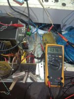
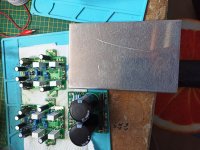
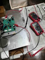
Thanks Bonsai, all measurements are at the same conditions.
Primary side connected, secondary side open circuit.
As you can see in pictures, i test 3 different transformers.
Picture 1 is the transformer that is used in Sx power supply.
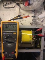
Picture 2 is another salvaged transformer from a UPS.
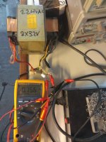
Picture 3 is a salvaged transformer from a hi-fi 5+1 receiver.
In all these cases the primary coil current, when the secondary coil is open, is high enough and the higher is this in the higher VA transformer (1)
Yes i know, the quality for those UPS aren't good.
Trying to solder wires at the secondary (in the past) i discover that aluminium wire used for the secondary instead of Cu.
As you can see in the 3rd picture, primary coil current is high even in this case, hi-fi transformer.
Is it possible that a high D.C voltage is present at the main?
All transformers are absolutely cold.
Primary side connected, secondary side open circuit.
As you can see in pictures, i test 3 different transformers.
Picture 1 is the transformer that is used in Sx power supply.
Picture 2 is another salvaged transformer from a UPS.
Picture 3 is a salvaged transformer from a hi-fi 5+1 receiver.
In all these cases the primary coil current, when the secondary coil is open, is high enough and the higher is this in the higher VA transformer (1)
Yes i know, the quality for those UPS aren't good.
Trying to solder wires at the secondary (in the past) i discover that aluminium wire used for the secondary instead of Cu.
As you can see in the 3rd picture, primary coil current is high even in this case, hi-fi transformer.
Is it possible that a high D.C voltage is present at the main?
All transformers are absolutely cold.
Last edited:
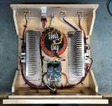
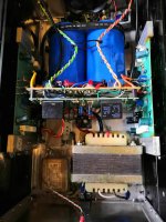
Well I'm ashamed to say but after almost 6 years I have finally installed the NX into a case. I had the Destroyer X Super A in this case and never really liked it so I decided to make a swap. I'm using a 34/0/34VAC Antek 600vA transformer. This is providing +-47VDC at the amp. Everything is working as it should. I adjusted the bias to 41mV across one 0R33 emitter resistor. This is a little lower than the recommended but my heatsinks are a little smaller that what Andrew used. I have had it playing music for about an hour and the heat sinks are at about 45c. Sounds lovely of course.
Attachments


Dear people,
I started building an SX amplifier over the weekend and the soldering is going quite smoothly.
I use WBT 0800 silver solder and it flows very well and has a relatively low melting point.
Expensive but worth working with.
Unfortunately I can't solder SX yet because I don't have the right 3.3 AXIAL0.5 R9 resistors.
On the BOM list they are not listed as 2W but on the circuit so I ordered the 0.5W resistors useless. I can order these from Reichelt, they are two expensive resistances.
I also find that C2 (SMD 10uF 50V) is not on the list, but I still had it.
I assume it needs to be soldered so I did this.
All in all soldering for a while and then testing and adjusting.
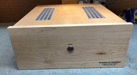
I want to build the SX amplifier in one chassis together with the Korg NuTube B1 preamp.
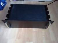
I bought this cabinet a while ago with the idea to build the SX fresher in it.
There is enough space in the chassis with the cooling for the NuTube and SX and it seems a nice combination.
THE 19 '' cabinet has a height of 4U and a depth of 230 mm. Manufactured from 1.5mm skinplate, 2.5mm aluminum back and 4mm aluminum front plate. The cabinet has a cooling profile of 165 (W) x230 (L) x40 (H) mm on both sides, each with a heat resistance of 0.425K / W.
The cooling of the radiators per radiator is 0.425C / W and that is slightly too little cooling according to the SX manual. Now I have two "heavy" aluminum plates of 20x13x7.5 mm thick about 0.525 kilos. On these plates I want to mount the SX amplifiers and mount these plates with thermal paste in between on the cooling elements of the cabinet. No idea where the cooling value will be? ... C / W. On the internet I use a calculator for a flat plate cooling calculation but I did not get the desired calculation.
Does anyone have an idea where I come up with the cooling as described or is there no point in tackling it this way?
I hope for some answers and wish you all a lot of building fun! With regards Frits
I started building an SX amplifier over the weekend and the soldering is going quite smoothly.
I use WBT 0800 silver solder and it flows very well and has a relatively low melting point.
Expensive but worth working with.
Unfortunately I can't solder SX yet because I don't have the right 3.3 AXIAL0.5 R9 resistors.
On the BOM list they are not listed as 2W but on the circuit so I ordered the 0.5W resistors useless. I can order these from Reichelt, they are two expensive resistances.
I also find that C2 (SMD 10uF 50V) is not on the list, but I still had it.
I assume it needs to be soldered so I did this.
All in all soldering for a while and then testing and adjusting.
I want to build the SX amplifier in one chassis together with the Korg NuTube B1 preamp.
I bought this cabinet a while ago with the idea to build the SX fresher in it.
There is enough space in the chassis with the cooling for the NuTube and SX and it seems a nice combination.
THE 19 '' cabinet has a height of 4U and a depth of 230 mm. Manufactured from 1.5mm skinplate, 2.5mm aluminum back and 4mm aluminum front plate. The cabinet has a cooling profile of 165 (W) x230 (L) x40 (H) mm on both sides, each with a heat resistance of 0.425K / W.
The cooling of the radiators per radiator is 0.425C / W and that is slightly too little cooling according to the SX manual. Now I have two "heavy" aluminum plates of 20x13x7.5 mm thick about 0.525 kilos. On these plates I want to mount the SX amplifiers and mount these plates with thermal paste in between on the cooling elements of the cabinet. No idea where the cooling value will be? ... C / W. On the internet I use a calculator for a flat plate cooling calculation but I did not get the desired calculation.
Does anyone have an idea where I come up with the cooling as described or is there no point in tackling it this way?
I hope for some answers and wish you all a lot of building fun! With regards Frits
Attachments
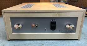
I finished my NX Amplifier. I am enjoying this amplifier in my shop system.
This was a learning project. I took my time and followed Andrew's build instructions and recommendations. I also followed his wiring guide "Preventing Hum and Noise Problem in Audio Amplifier" available on his website.
I want thank Andrew for his patience and personal support. I also had a lot of fun!
Attachments
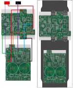
Connections layout
Hi,
can you please have a look on the way I made the connections and tell me if they are correct?
I tried to use, as much as possible, the colour schema used in Figure 21.
I need to put the PCB of the amplifier in that way, if I want to use a 3U HiFi2000 chassis.
Thanks
Hi,
can you please have a look on the way I made the connections and tell me if they are correct?
I tried to use, as much as possible, the colour schema used in Figure 21.
I need to put the PCB of the amplifier in that way, if I want to use a 3U HiFi2000 chassis.
Thanks
Attachments
Last edited:
Hi,
Perhaps a member can help me out with this.
I just managed to finish the repair of my SX amp that a friend built for me (he's not doing any repair work anymore). The unit is working now. Bias at 320mV across the 0.33Rs and steady. While I can dial down the DC offset to within zero now, the reading keeps bouncing around +14mv to -10mV. Though I don't hear its effect on the sound, and the unit has speaker protect modules, I'm not sure if it will further drift and ultimately do some damage. Can anyone explain why or whether it is normal for SX, and if not if there is a fix for this?
FYI, for me to adjust the offset and get to the zero target, I soldered a 1K resistor across the 10K (R1) next to the offset pot. Tried other values but 1K did the trick.
Would appreciate any input. Thanks.
Sorry, I just noticed my typo mistake. The bias is 420mV not 320.
"The unit is working now. Bias at 320mV across the 0.33Rs and steady."
"The unit is working now. Bias at 320mV across the 0.33Rs and steady."
Hi Bonsai,
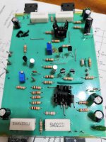
The PCBs were hand built by my friend, its not from Jim's Audio. The pics I uploaded are the only ones I managed to take during my struggle to fix the original problems - left channel dead, distorted right. So what you'll see will be ugly.
The PCBs are now mounted on the chassis, hence no latest pics. The unit works, except for my concern about bouncing offset readings. I bought Jim's PCBs on August 3 but got delayed due to the pandemic but its in the country now. I bought it in case I'm not able to fix the unit, or probably just build a new one.
I just want to get some suggestions as to where I have to look in case I need to dismantle again the current unit, or when the same problem arise when I use Jim's PCBs.
Danny
Attachments

The four input transistors need to be mounted close together to minimize 2nd order thermal gradient effects ( this is the delta of the Vbe delta between the 4 transistors). This will be a major reason for the output voltage bouncing around. It *may* improve once you box it up and the internal amplifier air currents are minimized and it thermally stabilizes.
Another important point here is this is a very wide bandwidth amplifier Your layout is definitely not optimized for that and I can see potential problems. The Jim’s Audio boards sell for c. $25 for 2 amp boards and a PSU board - I urge you to use them. The quality is very, very good and I designed them so you know what you are getting.
Sorry to be blunt, but your board is not good.
Peace
🙂
You are very right. The boards are not good. You haven't seen the backside yet. I was disappointed the first time I took it out of the enclosure. Jim's PCB will arrive soon. I already have all the parts from Mouser for a new build.
I get your point on optimizing the layout and importance of having the transistors close to each other. Thanks.
Anyway, the amp's SQ is fantastic even at a lower bias of 420mV.
Cheers
I get your point on optimizing the layout and importance of having the transistors close to each other. Thanks.
Anyway, the amp's SQ is fantastic even at a lower bias of 420mV.
Cheers
bias question
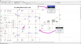
hi I just got a question about the bias for what I read R6 has to be adjusted to minimum so is 0 ohms? and then the bias adjustment is set voltage reading from R25 and R24 to be set to about 460mV? so that the flow of current to class A is set to 1.4A? "and yes the 30 minutes wait and verified got it" I just wanna be sure I got the simulation and is kind like showing that, another thing I clone I think is Alex MM's PCB design and I made it a bit modern also I was looking at the Jean Hiraga Class A and I saw the article from Bonsai lot of data make senses to build this one the Hiraga is nice but PSU is too expensive with this one the pocket doesn't suffer that much I guess 😛
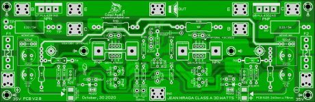
oh yeah I was doing this large layout of the Hiraga Class A I'm gonna posted here so you guys can see what "was" my idea looks cool right? 🙂
hi I just got a question about the bias for what I read R6 has to be adjusted to minimum so is 0 ohms? and then the bias adjustment is set voltage reading from R25 and R24 to be set to about 460mV? so that the flow of current to class A is set to 1.4A? "and yes the 30 minutes wait and verified got it" I just wanna be sure I got the simulation and is kind like showing that, another thing I clone I think is Alex MM's PCB design and I made it a bit modern also I was looking at the Jean Hiraga Class A and I saw the article from Bonsai lot of data make senses to build this one the Hiraga is nice but PSU is too expensive with this one the pocket doesn't suffer that much I guess 😛
oh yeah I was doing this large layout of the Hiraga Class A I'm gonna posted here so you guys can see what "was" my idea looks cool right? 🙂
Attachments
- Home
- Amplifiers
- Solid State
- SX-Amp and NX-Amp