according to the pot modification i removed C13, shorted R17 and modified R10 to 33k, that's all on the amp board, plus few components around the pot, 1k, 220pF and bipolar 25uF
How have you wired up?
few components around the pot, 1k, 220pF and bipolar 25uF
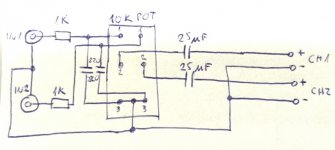
what do you mean? exactly like shown... 1k in series to the end of pot, 220pF paralell to the input of the pot, 25uF in series with the output (pot middle)... negative common, not mixing with chassis or supply...
something wrong there?
something wrong there?
Simple way..Use "paint" and draw a simple schematic,this will be more detail than trying to explain with the use of words.what do you mean? exactly like shown... 1k in series to the end of pot, 220pF paralell to the input of the pot, 25uF in series with the output (pot middle)... negative common, not mixing with chassis or supply...
something wrong there?
Last edited:
EVERY circuit connection between modules requires a TWO wire connection.what do you mean? exactly like shown... 1k in series to the end of pot, 220pF paralell to the input of the pot, 25uF in series with the output (pot middle)... negative common, not mixing with chassis or supply...
something wrong there?
Your description seems to be telling me all about ONE wire. Without a diagram I can only guess what you have done with the other wire.
From the Source (audio module A) to the vol pot (audio module B) there must be a two wire connection.
From vol pot to Power Amplifier (audio module C) there must be a two wire connection.
From Power Amplifier to Speaker (audio module D) there must be a two wire connection.
and finally for current to flow to the speaker it has to come from the PSU (audio module E)
This requires a further TWO sets of two wires connections, but in some/many cases two of the wires are combined into a PSU Zero Volts wire. This becomes a twisted triplet connection between E & C
Last edited:

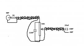
the difference is that there is coax from the rca to the resistor, and then from the bipolar to the amp input... but that shouldn't be such a problem, right?
The coax gives you your two wire connection. BUT !!!! the coax must be connected at both ends.
You also need to add ground referencing resistor to the input side of the bi-polar coupling capacitors. i.e. between the vol pot wiper and the 25uF. This ground referencing resistor takes leakage current though the bi-polar to audio ground and prevents a charge building up on the vol pot side of the cap.
Most would use the resistance of the vol pot wiper to audio ground to do this. But using a 1M or 2M2 as a real resistor plays safe with not passing a DC current out through the wiper.
With the vol pot and the input isolated from the PCB for all DC currents, you can do what you like before that and it will not affect the amplifier's output offset.
Set the output offset with the 25uF in place. Then it not change significantly, but it will wander, particularly during warm up, or when you allow a waft of air to pass over the input transistors.
Last edited:
thanks for the help and the advices, but i had to wrap it up for now and will continue after one month, no time anymore...
until then i will use some time to figure out what to do and how, but most important for now is that the amp boards work just fine, only the pot integration is giving me trouble, but it will get done somehow for sure...
until then i will use some time to figure out what to do and how, but most important for now is that the amp boards work just fine, only the pot integration is giving me trouble, but it will get done somehow for sure...
Guys,
D15 turns on instantly when powered up and does not turn off when battery is applied on J10...... What could be the problem?
PS The two power indicator LED's are VERY bright....
Help????
D15 turns on instantly when powered up and does not turn off when battery is applied on J10...... What could be the problem?
PS The two power indicator LED's are VERY bright....
Help????
BIG misstake.... both U1 and U2 fitted with PDTC144's..... I knew I needed new glasses 🙂
And I followed the BOM for R21 and R22... so now my eyes hurt 🙂 I will change these for 10K resistors.......
And I followed the BOM for R21 and R22... so now my eyes hurt 🙂 I will change these for 10K resistors.......
Progress!
All is well here with the PSU and amp boards. Measurements are by the book!
Soon I will post some pictures when I start assembling the amps casing. Looks very promising.
Now I have to wait for some last parts to arrive. I want to change the 22000/50 volt caps to 63 volts. Better ripple that way. But Mundorf's stock is depleted and I have to wait a while for the good stuff.
Cheers!
Busy times over here 😀 Yes, I should finish my dissertation..... but I have a little update to share: I've bought two very nice, chunky Mundorf 22 mF capacitors!
I've also just obtained an Amplimo 2 x 35VAC, 500VA toroidal transformer Amplimo 88018. I guess it won't harm, but to be shure, is 2x 35V AC still okay Bonsai?
Kaplaars, where did you buy those little heatsinks on the rectifiers?
- Home
- Amplifiers
- Solid State
- SX-Amp and NX-Amp