ok, so far so good...
it seems that was the issue, reversed C6. the thing is that original board doesn't have that cap properly marked, no polarity shown on the board and i looked on the photo of the board v1 from the manual insted of the layout, i was just hoping i didn't burn anything and it seems i didn't.
i didn't test with the speaker, only 8ohm resistance and everything seems to be in order... need to modify and test the other channel also, will do in the next days, keep you posted on the progress 😉
Reversed Zener capacitor (C6) means it leaks badly. Since it is maximum of 10Vdc it may not explode. But it is likely to be damaged.
Replace with a newly reformed capacitor.
Replace with a newly reformed capacitor.
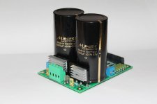
Busy times over here 😀 Yes, I should finish my dissertation..... but I have a little update to share: I've bought two very nice, chunky Mundorf 22 mF capacitors!
I've also just obtained an Amplimo 2 x 35VAC, 500VA toroidal transformer Amplimo 88018. I guess it won't harm, but to be shure, is 2x 35V AC still okay Bonsai?
I've also just obtained an Amplimo 2 x 35VAC, 500VA toroidal transformer Amplimo 88018. I guess it won't harm, but to be shure, is 2x 35V AC still okay Bonsai?
Attachments
incredible stuff happening with my project, today i changed the C6 as AndrewT suggested (although measured good value, 970uf), but with the used one and was testing for about an hour and suddenly lost negative half-period of the signal, switched it of quickly because i thought the problem was with the supply and while testing is made a short with a nice blast and burned the primary... i was so frustrated, thinking what to do, no spare trafo, of course, and it was toroidal, at first i thought just to give up for today tomorrow and search for some winding company to fix it, but i decided to give it a try myself, nothing to lose... unwound few rounds to make room for primary connection and found the problem, wire just got unsoldered, fixed it, rewound the wire and voila, back on the power track 🙂
but anyway, the problem was not the supply, found the "new" C6 dead with no spare and now need to buy two new to replace tomorrow and hopefully make final testing and slowly start assembling the box...
uffff, so far it's been a funny mix of satisfaction and frustration, i just hope it will get only better from tomorrow, i have really high hopes for this amplifier...
Livin on the edge Crnipetar 😉. Hopefully it works again when C6 is replaced. Are you sure the rest is OK and properly fitted? Maybe you can upload a few high resolution pictures of your boards so it can be checked 🙂.
yeah, so far it's good, i've changed the caps and both channels again work as they should, but still haven't tested with speakers 🙂
i'm pretty sure everything is fitted nicely, only few (but cardinal) mistakes (C6 and clumsy short on the PSU), but they are corrected now 😀
will try to take the pictures tomorrow 😉
i'm pretty sure everything is fitted nicely, only few (but cardinal) mistakes (C6 and clumsy short on the PSU), but they are corrected now 😀
will try to take the pictures tomorrow 😉
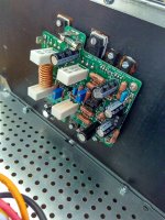
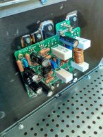
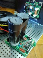
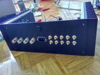
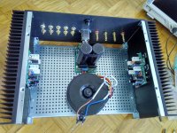
here are some photos of current progress, i think i will put it on hold for a few days now and continue next week...
still missing the installation for input selector switch and pot, but i plan to make it in a different way than usual, will show it when it will be (hopefully) done 🙂
still missing the installation for input selector switch and pot, but i plan to make it in a different way than usual, will show it when it will be (hopefully) done 🙂
Attachments
Hi Bonsai
Reference to alternatives suggested in post#1790
I found couple of pairs ksc2690 & ksa1220 transistors with hfe and vbe closely matched (though vbe not as close).. ksc2690 (hfe 257, vbe .475mv), ksa1220 (hfe 248, vbe .462mv)
For sx-amp can i go ahead and use these?
1.for Q6 - KSC2690 in place of KSC3503
2. for Q7 - KSA1220 in place of KSA1381
Vbe in a driver pair is not as important. hFE minises the current imbalance drawn/injected from the preceding stage.
For paralleled transistors Vbe becomes VERY important. The same applies to LTP assemblies.
For paralleled transistors Vbe becomes VERY important. The same applies to LTP assemblies.
here are some photos of current progress, i think i will put it on hold for a few days now and continue next week...
still missing the installation for input selector switch and pot, but i plan to make it in a different way than usual, will show it when it will be (hopefully) done 🙂
Nice work! It seems like that C13 is missing. Why is that? Or is it attached to the bottom side?
no no, it's not missing, the boards are already modified for the use of the pot, in that case i had to remove C13 and R17 and change R10 to 33k, like it says in the end of the manual 😉
btw, thanks 🙂
btw, thanks 🙂
problem again...
i'm using the pot connection as shown in the manual and currently using mobile phone as source for testing. the problem is that i have constant 1.1 V dc offset at the ouputs, regardless of the position of the pot. but when i make a short directly on the amp input i get a good 0 V on the output.
what could be the problem, any idea?
(btw, for the bipolar cap i use the substitute connection with 2 reverse polarized in series and 1 polyester cap parallel)
Check your mobile phone out - might be using a BTL OPS.
What value pot are you using?
Have you used a DC blocking cap?
What value pot are you using?
Have you used a DC blocking cap?
how do i check my phone for that? 😕
pot is 10k and only blocking cap is the bipolar (improvised), shouldn't that be sufficient for dc blocking?
pot is 10k and only blocking cap is the bipolar (improvised), shouldn't that be sufficient for dc blocking?
Check your phone output(FOR D.C PRESENCE) when playing music using a voltmeter at d.c scale.
Last edited:
i wasn't even playing music, only had it connected and paused when tested the output...
now i've checked it and it's fine, 0.0 - 0.1 mV during pause...
now i've checked it and it's fine, 0.0 - 0.1 mV during pause...
it's clear now why i have such offset, the voltage on J2 is 27 mV and that corresponds to 1.1 V on the output...
should i bypass J2? the drawing says not to put the link and nowhere in the manual can i find any other info, to put or not... what would be the correct way to go?
should i bypass J2? the drawing says not to put the link and nowhere in the manual can i find any other info, to put or not... what would be the correct way to go?
j2 should not be needed.
If you leave the input open, then the +IN sees a different voltage from the -IN. That gives an output offset.
If you short the input, or connect it to a very low source impedance, that brings the +IN voltage very close to the -IN voltage and you end up with virtually zero output offset. That is normally what you would see if your vol pot is set to near zero and/or your Rs is low say <200ohms.
If you connect a Source and you get an offset, then that can be due to a high Rs, or due to output DC from the Source.
All these problems go away when the Power Amplifier is AC coupled.
NX is DC coupled.
You need to be able to switch off your source so that output offset does not float to some higher value. The standard way would be to convert the NX to AC coupled, or turn your vol pot down to zero.
You can add a DC blocking capacitor at the input and reset the output offset to near zero. This gives you a mixed AC & DC coupling. This is waht I have done. It's not great, you see the output offset wandering around but still low enough that it can be ignored.
Full AC coupling would require a very large electrolytic in the NFB line, but the low 15r there requires many mF of electrolytic.
Last edited:
thanks for the reply, AndrewT...
but still i don't really get it, regardless of the source, connected or open, pot min or max, i have the same offset... only when i bypass the bipolar cap after the pot it drops to zero, everything is ok... wtf?
but still i don't really get it, regardless of the source, connected or open, pot min or max, i have the same offset... only when i bypass the bipolar cap after the pot it drops to zero, everything is ok... wtf?
- Home
- Amplifiers
- Solid State
- SX-Amp and NX-Amp