Just go ahead 🙂 There are people who can help if you get lost. Bonsai helped me.
But these "issues" have been sorted out and commented in the first post here.
Feel free to message me. (In Norwegian). 🙂
But these "issues" have been sorted out and commented in the first post here.
Feel free to message me. (In Norwegian). 🙂
Hi guys
I have a problem with power supply.D15 still shines.I am sending scheme with voltage.2N7002 is ok.Thanks for help
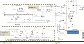
I joined the J10 DC Voltage 1.5V and the LED lights up constantly. Protection does not work.What's wrong???!!!
There is something completely wrong with this Joel. The adjustmrnt should be smooth and the Iq stable. Somewhere on this thread is a plot of Iq vs time done by a builder - it's very stable.
If you cannot get these going, you can mail them to me and I will take a look. I will only be able to do this in November though because all my stuff is in a ship until end October.
Really sorry you are having this issue.
For NX:
Q3 on amp board calls for part BC847CT,115 NXP Semiconductors | Mouser
But I'm using BC847C RF Taiwan Semiconductor | Mouser
Cant see any issue(according to data sheet) with Q3 but now grasping at any possibility as to why I had trouble debugging my amp in September.
Need to order a few parts and plan to take another stab at it.
I bought bc850c for another project some while back.
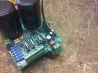
They also seem to work OK. Except for the lack of temperature monitoring due to the gap between the Q3 and the output devices.
I have since modified both my boards to glue Q3 upside down to the collector lead of the adjacent output.
This modified arrangement is slightly overcompensated. But the thermal connection and time lag is much improved.
To reduce the tempco, I have just added a 47r 805 resistor in series with the emitter trace of Q3, but not yet tested. Report soon. Might take a while to find the right value of that resistor.
I tried to find a way to extend the emitter trace through new holes in the PCB, but there are too many traces in that area. This would have made tempco experimentation much easier.
No, it still there. Bonzai said he would look at it, I'm still waiting for a solution.
Sometimes it sends an SC message to the PSU PCB and turns on the SS relay and the red warning LED.
But turning off the amp and powering back on does not defeat the SS relay.
It needs the PSU smoothing to discharge to near zero volts to allow the SS relay to untrigger.
That needs many minutes. Or take the lid off and manually add a 50r resistor to discharge each cap bank.
AndrewT,
I have not had any oscillation problems on any of the builds I have done - the amplifiers are very stable. You may get a slight squeal at a very low level as you power down since when the supply rails are at a few volts, all bets are off as to how the amplifier is behaving - but if you have built the protection boards and the speaker is disconnected, you won't get this as the speaker will be disengaged.
I am still trying to understand why you have a thermal problem. Use a bit of thermal;compound as we discussed in an earlier thread if you feel you must have tighter comp. Obviously the size of your heatsinks will have a bearing on the comp as well.
Andrew
Joe I have sent you a PM
Than you. I responded.
I'll wait until you read my PM before I power up again.
Joel
Bonsai, and my problem..thanks
http://www.diyaudio.com/forums/solid-state/236522-sx-amp-nx-amp-166.html#post4580651
I joined the J10 DC Voltage 1.5V and the LED lights up constantly. Protection does not work.What'sng???!!!
http://www.diyaudio.com/forums/solid-state/236522-sx-amp-nx-amp-166.html#post4580651
I joined the J10 DC Voltage 1.5V and the LED lights up constantly. Protection does not work.What'sng???!!!
Hello platon.rado
After you power up, D15 should come on after a short delay (5 seconds or so, but may be longer depending on your PSU specifics) and should go off about 1 second after you turn the power switch off.
Can you confirm what you are seeing D15 do?
After you power up, D15 should come on after a short delay (5 seconds or so, but may be longer depending on your PSU specifics) and should go off about 1 second after you turn the power switch off.
Can you confirm what you are seeing D15 do?
Right after source connection,D15 lights.Still shines.After connecting 1.5V J10 D15 lights.And still shining...
Matching C3503E/A1381E
Hello everyone,
I just bought 10 pairs of C3503E/A1381E. The hFE on the 1381s (tested on a DMM) are between 172 and 175; the 3503s read 135-142.
Are these close enough for the sx-amp? Or do I need to invest in 50 pairs like Andrew T. did and hope for the best?
Thanks!
Amit
Hello everyone,
I just bought 10 pairs of C3503E/A1381E. The hFE on the 1381s (tested on a DMM) are between 172 and 175; the 3503s read 135-142.
Are these close enough for the sx-amp? Or do I need to invest in 50 pairs like Andrew T. did and hope for the best?
Thanks!
Amit
Platon, for your D15 problem, please look at the following
1. make sure C2 and C10 are installed correctly and working - if not, you will not have any delays
2. measure the voltage between 0V and the anode of D17 (4.7V Zener) - it should be between 3V and 4.7V after you have powered up.
3. Connect your meter between 0V and the drain of Q3. On switch on it should be close to your V+ voltage, and then after 5-10 seconds switch low. If it is doing this, then Q1 is probably faulty.
Amit, with this big difference in hFe, you will probably have problems in adjusting the offset. In this case, change R1 (10k) to 4.7k. I would only do this if you cannot adjust the offset with R1=10k
- Home
- Amplifiers
- Solid State
- SX-Amp and NX-Amp