I don't have 22ohms on hand. Is 15ohm ok? Have some 0.5w spare of those... (from removal of R4 since it was a fault in the pcb) 🙂
BTW: I am sure I can connect them under the psu pcb.
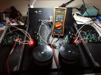
And got +-25Vdc from the PSU's.. A bit on the high side unloaded. Got a good and deep 4u case with good heatsinks.
BTW: I am sure I can connect them under the psu pcb.
And got +-25Vdc from the PSU's.. A bit on the high side unloaded. Got a good and deep 4u case with good heatsinks.
Last edited:
The amp builds are complete.Andrew_T, did you ever complete your build? If yes, do you like it?
Ciao!
Do
But testing with shorted input revealed a problem.
That problem became much worse when I installed the heatsink into the chassis.
It took a while to realise that parasitic capacitance of the chassis was causing this intermittant oscillation. That is now attended to. Pulling the mains plug out did not help either.
But there remains an oscillation problem during start up and for a very extended period during shut down.
The amp goes into full blown oscillation as the PSU supply voltage drops. This behaviour is affected by whether the SS relay is ON or OFF.
And because the SS relay leaves a capacitive coupling to the output leads, the HF oscillation gets straight into the load and the scope probes.
It makes little difference whether the 8r0 load is connected or disconnected, it makes no difference whether the input is shorted or connected to the signal generator.
I have used 10r for R41 & R42, even though the current recommendation is for 0r0. That allows me to check base current of the drivers.
I'm still scratching my head (I'm not good at this AC stuff) about why an unconditionally stable amplifier goes into oscillation on reduced supply voltage.
Last edited:
The diode bridge passes fault current to PE. The resistor passes low levels of interference to the Chassis.I don't have 22ohms on hand. Is 15ohm ok? Have some 0.5w spare of those... (from removal of R4 since it was a fault in the pcb) 🙂
BTW: I am sure I can connect them under the psu pcb.
And got +-25Vdc from the PSU's.. A bit on the high side unloaded. Got a good and deep 4u case with good heatsinks.
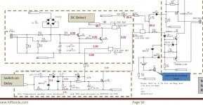
A have tested a 35A bridge rectifier with a 600mW 10r resistor in parallel and a 100nF capacitor in parallel to full mains direct across the Disconnecting Network and could detect no damage to any component. The fuses and holders blew up during this test with an almighty explosion. Much of the two fuses were never found. Did they vaporise with the fault current energy that passed for those few microseconds?
But this does make the point that the diode bridge is absolutely vital, if you do decide to implement the Disconnecting Network.
Almost there.
SX Amp is more or less finished. However got an issue when powering up.
Across +V fuse holder I measure 330mA (as it should be) when R6 is at max.
However I am unable to change this measurement when dialing R6.
It stays at ~330mA no matter what I do with R6.
This is for both channels.
I am pretty sure 🙂 everything is as it should be 🙂
Best regards.
Attachments
Last edited:
I am a little further forward with trying to ensure no oscillation for the NX I have built up.
I discovered that the _IN side of the RF attenuation capacitor is VERY sensitive to a finger touch. The amp instantly bursts into full oscillation. On releasing it sometimes stops and returns to normal and sometimes I have to pull the plug out.
Does this indicate a damaged component somewhere in the front end?
Any idea why it is so sensitive to a bit of parasitic capacitance?
I have added 680pF MKP in parallel to the 220pF used for C13.
This helps a bit. But I still get occasional oscillation at start up and always at shut down.
Last edited:
I am a little further forward with trying to ensure no oscillation for the NX I have built up.
I discovered that the _IN side of the RF attenuation capacitor is VERY sensitive to a finger touch. The amp instantly bursts into full oscillation. On releasing it sometimes stops and returns to normal and sometimes I have to pull the plug out.
Does this indicate a damaged component somewhere in the front end?
Any idea why it is so sensitive to a bit of parasitic capacitance?
It does suggest the gain or phase margin of your unit is inadequate. Measure all the smallish compensation capacitors for correct value and verify their connection integrity.
In the version 2.09 document I see that frequency compensation is done in LTspice and some time domain measurements were done to try to confirm the results. The best way to do this kind of measurement is with a network analyzer but that is a rather expensive piece of equipment that very few DIY folks have access to. If there is any inaccuracy in the LTspice model it may not be correctly predicting bandwidth, gain margin, and phase margin.
I had an interesting problem bringing up my NX amplifier that may be somewhat related to your issues. My build includes a stepped attenuator in the box with the amplifier. The RCA jacks are insulated from the chassis and there is wiring from the jacks to the attenuator and then to the amp boards.
On the lowest attenuator switch setting (maximum attenuation) I could hear the local FM station at 100 MHz through the speakers. How the amplifier demodulated an FM signal is a mystery (slope detection?) but there it was. The DC offset at the amplifier output also rose a few tenths of a volt under these conditions.
To cure the problem I changed all the input wiring in the amplifier box to shielded twisted pair and added .01uF capacitors from RCA jack ground to chassis right at the jacks.
Input are a matched quad set of BC546c/556c
TIS are 2sa1381e/c3503e
Drivers are 2sa1220ay/c2609ay
Outputs are mjl4302/4281
R40/41 are 10r
TIS are 2sa1381e/c3503e
Drivers are 2sa1220ay/c2609ay
Outputs are mjl4302/4281
R40/41 are 10r
Ok - thanks.
I will have to take a look - I did not have any problems on my builds but it concerns me if you have an issue.
I will have to take a look - I did not have any problems on my builds but it concerns me if you have an issue.
Bonsai
Sorry for spamming in your thread but I am looking a small advice.
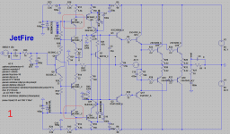
I am working on the very simple CFA, very basic one. Bellow posted two schematics:
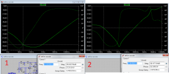
1.Includes extra cascoding transistor --> the PSSR at the low end looks a lot better.
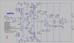
2.Cascoding transistor is not present --> the PSSR looks way worse in this case at lower end.
My question is noise related: can I connect the bases of the cascoding transistors (marked in red boxes) to the zener reference +/-15V (the low noise zeners bzx55 series) ?
Or better to look for some other voltage reference (resistor divider) for the cascode transistors ?
Big thanks.
Peter
Sorry for spamming in your thread but I am looking a small advice.
I am working on the very simple CFA, very basic one. Bellow posted two schematics:
1.Includes extra cascoding transistor --> the PSSR at the low end looks a lot better.
2.Cascoding transistor is not present --> the PSSR looks way worse in this case at lower end.
My question is noise related: can I connect the bases of the cascoding transistors (marked in red boxes) to the zener reference +/-15V (the low noise zeners bzx55 series) ?
Or better to look for some other voltage reference (resistor divider) for the cascode transistors ?
Big thanks.
Peter
Attachments
Hi After running NX amp for one month I can see its sounding wonderful and stable dc offset which is now become less than 2 mv for both channels.
Bonsai
Sorry for spamming in your thread but I am looking a small advice.
I am working on the very simple CFA, very basic one. Bellow posted two schematics:
1.Includes extra cascoding transistor --> the PSSR at the low end looks a lot better.
2.Cascoding transistor is not present --> the PSSR looks way worse in this case at lower end.
My question is noise related: can I connect the bases of the cascoding transistors (marked in red boxes) to the zener reference +/-15V (the low noise zeners bzx55 series) ?
Or better to look for some other voltage reference (resistor divider) for the cascode transistors ?
Big thanks.
Peter
Hello Peter,
yes, you can connect your cascode as shown in your fig 1. I am doing the same thing in some of my new designs. The main advantage is you get the same voltage drop across all the diamond transistors, and if you run them at the same current (for me that's 1-1.5mA), you get good thermal balance and tracking, so the drift is then low. I have not specifically looked at the PSRR improvements you have noted, but based on other designs (e.g. like Blamleess) I would expect there to be some improvements.
sx-Amp builders: there is an error in the write-up. R20 is shown as 1k in the circuit diagram should be 2.2k. I will add an errata to the first post on this thread.
Bonsai
Big thanks.
I am running all ''diamond'' trannies at the very similar current, so should be fine.
Now time to do some PCB work. I like a lot yours offset adjustment (IMHO better than ballancing the front stage currents). If You don't mind I will adopt to my schematic.
Regards
Peter
Big thanks.
I am running all ''diamond'' trannies at the very similar current, so should be fine.
Now time to do some PCB work. I like a lot yours offset adjustment (IMHO better than ballancing the front stage currents). If You don't mind I will adopt to my schematic.
Regards
Peter
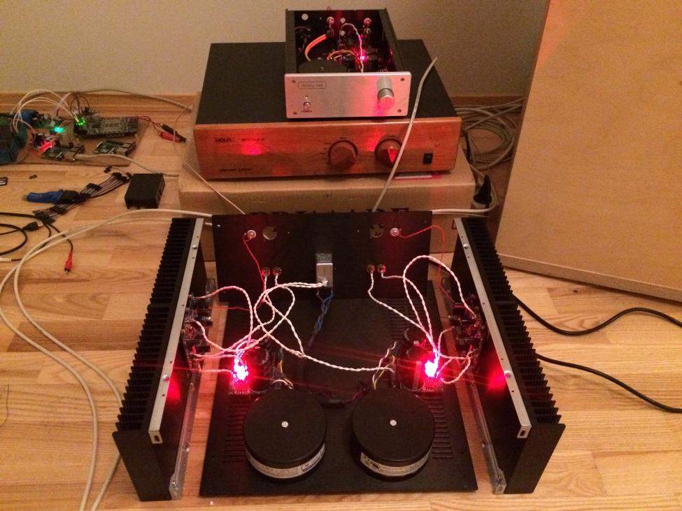
SX amp soon finished. After some module testing I just had to connect it.
Not finished tidying up and all that.
Initially with a soekris r-2r dac into dcb1 preamp into SX amp.
Then I took the dcb1 out of the chain and dac into SX amp.
This is a really really nice amp!.
I have had some issues but almost all are sorted out.
Will take out the scope in a day or two to test it.
Its sitting in a 4u case.
One question.
I am also looking for a ~100W class AB amp to build. I have slewmaster pcbs (thinking of a 3 pair version) and Kypton-nd IPS for it.
Shall I build that one or ditch it in favour for an Ovation-nx? Has anyone compared these two amps?
SX amp soon finished. After some module testing I just had to connect it.
Not finished tidying up and all that.
Initially with a soekris r-2r dac into dcb1 preamp into SX amp.
Then I took the dcb1 out of the chain and dac into SX amp.
This is a really really nice amp!.
I have had some issues but almost all are sorted out.
Will take out the scope in a day or two to test it.
Its sitting in a 4u case.
One question.
I am also looking for a ~100W class AB amp to build. I have slewmaster pcbs (thinking of a 3 pair version) and Kypton-nd IPS for it.
Shall I build that one or ditch it in favour for an Ovation-nx? Has anyone compared these two amps?
The Kypton ND is the NX on steroids. I have built both. It just depends on what you are looking for. You will not "hear" a difference between then. The distortion is so low on both it is undetectable and they are both super fast. The NX was the inspiration for the Slewmaster CFA vs VFA battle. If you only need 100W the NX is all you need and cheaper to build. Smaller PSU, smaller heatsinks and less parts. If you want a party amp the Slewmaster would be hard to beat.
Blessings, Terry
Very nice Magnus!
I will ping you separately to make a list of the issues so I can issue a full errata.
Please let us know more fully the sound when you are done. I understand you are using some very high efficiency FR speakers - good match for the sx-Amp.
I will ping you separately to make a list of the issues so I can issue a full errata.
Please let us know more fully the sound when you are done. I understand you are using some very high efficiency FR speakers - good match for the sx-Amp.
Terry,
Yes indeed the nx-Amp did trigger a lot of activity on CFA's on the forum with many designers experimenting with New CFA designs.
Glad you liked your amps!
Happy Listening!
Yes indeed the nx-Amp did trigger a lot of activity on CFA's on the forum with many designers experimenting with New CFA designs.
Glad you liked your amps!
Happy Listening!
- Home
- Amplifiers
- Solid State
- SX-Amp and NX-Amp