Thanks jwilhelm. I was hoping there was an Excel file so that it can be uploaded to the various suppliers. I noticed that it's no longer available on the hifisonix site but was wondering if anyone had a copy.
Another small "fault/difference" between the sx pcb and manual.
On the pcb from jims audio it says R20=220r.
The manual says R20=1k
I guess that the manual is correct here.
On the pcb from jims audio it says R20=220r.
The manual says R20=1k
I guess that the manual is correct here.
V2.10 Corrected value of R20 from 220 Ohms to 1k. Added distortion
plots; added single sided layout
The last post is not editable anymore.
However one more thing.
R4 according to pcb and "drawing" of the pcb in the manual says 100k.
The BOM in the manual says r4=15r
According to the schematic is is supposed to be 15r.
I guess it shall be 15r?
It is not mentioned anywhere else in the manual.
However one more thing.
R4 according to pcb and "drawing" of the pcb in the manual says 100k.
The BOM in the manual says r4=15r
According to the schematic is is supposed to be 15r.
I guess it shall be 15r?
It is not mentioned anywhere else in the manual.
Last edited:
Another small "fault/difference" between the sx pcb and manual.
On the pcb from jims audio it says R20=220r.
The manual says R20=1k
I guess that the manual is correct here.
bambadoo - correct. R20 was increased to 1k reduce the adjustment range and prevent too much current to flow if you did not adjust R6 for Max (i.e 1k).
I have had the same feedback on the nx-amp - will make the updates when Jim does another batch of boards.
The last post is not editable anymore.
However one more thing.
R4 according to pcb and "drawing" of the pcb in the manual says 100k.
The BOM in the manual says r4=15r
According to the schematic is is supposed to be 15r.
I guess it shall be 15r?
It is not mentioned anywhere else in the manual.
Correct - R4 is 15 Ohms.

Hi everyone,my first post in this thread. (I know I'm late-story of my life ) I am considering building the SX version but I would really like a bit more class A power. Is it possible to increase the output to 25W RMS into 8 ohms from the normal 15W?
If so does anyone have the details
Thanks
Alan
If so does anyone have the details
Thanks
Alan
alibear,
unfortunately you cannot increase the power of the sx-Amplifier like this. note that the peak class A power of the sx-Amp is about 28 Watts
unfortunately you cannot increase the power of the sx-Amplifier like this. note that the peak class A power of the sx-Amp is about 28 Watts
Wow Bonsai, that was a fast response, thank you for your answere, much appreciated.
Regards
Alan
Regards
Alan
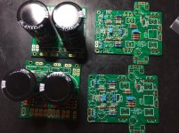
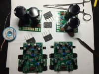
Not happening much but the sx pcbs are more or less finished. Mechanical work to do in 2016
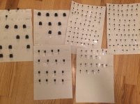
Bastard work matching transistors 🙂
Bastard work matching transistors 🙂
Attachments
Last edited:
very nice work,Waiting for your final build pictures with listening impressionshttps://www.google.co.in/search?q=l...X&ved=0ahUKEwiVuoaJgv7JAhVHGI4KHTSoD00QsAQIMg
My thanks to builders Vinnie from Italy, and Bambadoo from Norway for picking up the R4 error. R4 should be 100 k and not 15 ohms as I posted in an earlier erratum. This confusion came about from an earlier version of the board. I have updated the 1st post to reflect this.
Separately, it was reported that the offset could not be completely dialed out on some amplifiers. I will come back on this in the next few days.
Separately, it was reported that the offset could not be completely dialed out on some amplifiers. I will come back on this in the next few days.
Not happening much but the sx pcbs are more or less finished. Mechanical work to do in 2016
Bastard work matching transistors 🙂
Wow - very nice build so far!
Thanks.. Getting closer 🙂

BTW: One issue:
In the manual page 32 for sx amp it says:
So a ~22ohm resistor between the psu pcb (0V) and chassis ground will do the trick?
Best regards.
BTW: One issue:
In the manual page 32 for sx amp it says:
The PSU pcb from Jims audio do not have this incorporated as I can see.On the chassis mount terminal block you can see in Photo 3 towards the top LHS of the transformer, I wired in a 22 Ohm 0.5 W resistor between the power supply 0 V and the chassis – i.e. in parallel with the ground lifter. The latest PSU updates have incorporated this resistor on the PCB.
So a ~22ohm resistor between the psu pcb (0V) and chassis ground will do the trick?
Best regards.
Last edited:
- Home
- Amplifiers
- Solid State
- SX-Amp and NX-Amp