Sorry, I have been offline for c. 3 weeks - finally got internet here at my house in England.
The comments re the PSU +Protect board are noted. I will update the docs.
Thank you for your feedback.
The comments re the PSU +Protect board are noted. I will update the docs.
Thank you for your feedback.
1. Direct coupled and decent offset without a servo circuit.
2. Relatively low parts count and pretty much symmetrical schematic.
3. CFA design with wide bandwidth.
4. No "unobtanium" parts and PCB's available.
5. Excellent single .pdf document with everything in one place, so no need to sift through 1000's of forum pages to get all the key info.
The last 2 items are what really sealed the deal for me.
Bonsai, Thanks for all your work on this and for sharing!
😎🙂
-RNM
Stumped by a start up fault -AC Detect
Built up the first amp and PSU PCBs.
Started to follow the guide PSU testing.
The middle LED (Green) did not turn on. The mosFET relays were open circuit.
I spent a long time checking top side voltages. Went to bed.
checked the top side volatges again. Still no reason for the OFF condition.
Turned the PSU PCB upside down and started checking all the smd pin voltages.
Still no success. Went to bed.
Third day !
checking top side and bottom side again.
and using the U1, U2, U3 & LED voltages worked out it was the AC detect that was holding the relays OFF.
I had some kind of intermittant contact in the AC supply from the secondaries to the PCB. A screw down was not quite tight enough.
The PSU PCB had full and equal +ve and -ve supplies and yet the AC detect was not turning ON.
Now sorted. But three half days lost !
The three days were not lost but spent learning and understanding the circuit better. The times I have been the most frustrated with an amp were the times I learned the most. It's the beauty of diy. I'm glad you got it worked out and hopefully someone else will benefit from what you learned and shared.
NX amplifier live
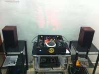
Finally NX amplifier got Live now.NX driving spendor s3/5 SE Bookshelf speakers.
Preamp:- DIY Akido tube Preamp with 4 6922 tubes
Bonsai excellent work.Really awesome performance separation,details with excellent mid.A complete power amplifier.I have used many amps to drive spendor but not fully satisfied now its perfectly matched. Really enjoying music now.
Attachments
Wow-very nice hifiramr! WIL you post some more pics up in the gallery?
Very nice looking build. Congrats!
🙂
Very nice looking build. Congrats!
🙂
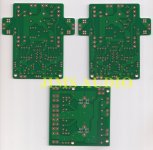
sx-Amplifier double sided THP gold flashed boards are now available from Jim's Audio here:-
15Wx2 class A 25Wx2 class AB Ovation sx-Amplifier Current Feedback PCB set !
They cost C. $25 for a set of two boards and a basic PSU
My thanks to Stanton for making these available.
😎
15Wx2 class A 25Wx2 class AB Ovation sx-Amplifier Current Feedback PCB set !
They cost C. $25 for a set of two boards and a basic PSU
My thanks to Stanton for making these available.
😎
Thank you Bonsai will post more pictures in coming days also its very happy news that pcb for 15W are available in jims audio
This is a very good news!sx-Amplifier double sided THP gold flashed boards are now available from Jim's Audio here:-
15Wx2 class A 25Wx2 class AB Ovation sx-Amplifier Current Feedback PCB set !
They cost C. $25 for a set of two boards and a basic PSU
My thanks to Stanton for making these available.
😎
I see members builting NX amplifier but not SX.
Now it's time for SX
RECOMMENDED.
Nice. SX amp pcbs ordered. Projects starting to pile up. Have been looking for approx 15-20w amplifier kit for a while now and the SX intrigued me.
However I am not into pcb etching just yet and really liked that it is now on sale..
I notice that the BOM (excel file) is missing from hifisonix site.
http://hifisonix.com/wordpress/wp-content/uploads/2014/02/sx-Amplifier-BOM-Excel.xls
Before I get into reading the whole "story" and this thread:
What is the maximum rail voltage recommended for this design? (was it 22vdc). I have on hand a couple of good smps at +-24 vdc. Is it to much or isn't smps (good quality) recommended for this design?
Otherwise i am thinking of ordering a couple of 18-0-18V 250VA transformers (good price for that rating).
More quiestions will follow but not yet 🙂
And again, thanks for this.
Please download the pdf file that contains all the details including BOM.This is the one of the great advantage given by Bonsai.Everything in his pdf file.
Happy Build
Happy Build
Downloaded and reading it. And of course this thread. Alot about the nx amp. Little about the sx but of course there are alot of similarities 🙂
In the manual it says:
Trying to make a decent BOM (.xls) file with components that are in stock.
In the manual it says:
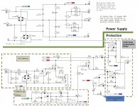
I am unable to find these caps in the BOM for the psu boards. (therefore uncertain about the casing for these caps...)Referring to Fig 14, the transformer AC secondary’s are fed into a 25 A PCB mount rectifier D4.
C4, C5, C7, and C8 (1 uF 50 V MLCC types)
Trying to make a decent BOM (.xls) file with components that are in stock.
the 1uF 50V are smd X7R in 1206 package.
One is on the front and labeled C14, no value. Two are on the back, but unlabeled.
I can't see them in the V2.0 BoM.
One is on the front and labeled C14, no value. Two are on the back, but unlabeled.
I can't see them in the V2.0 BoM.
Thanks. However this is for the sx amp PSU board bought from Jims audio.
There are 4 marked labeled on the back of the pcb. Cannot find anything on the front.
Measured on the pc screen with a ruler 😱 and compared to the 10mm holes (for the big caps).. Looks like the case should be approx 5mm and maybe approx 2.5mm wide?
Looks like C2 on the sx boards also is a smd cap. According to the BOM it is stated as C1. (Schematics says C2). (10uf, 6.3v MLCC 1206 package) So maybe a small fault in the Bom in the v2.09 manual for the sx?
Attachments

Sorry, I thought you were referring to NX.
I see one big SMD location on the back. Is that a capacitor?
What is that component next to Q2's base pad?
I see one big SMD location on the back. Is that a capacitor?
What is that component next to Q2's base pad?
Last edited:
- Home
- Amplifiers
- Solid State
- SX-Amp and NX-Amp