The resistors I am referring to are the feedback resistors (1.5k) - they should dB 0.5,W because at full power they dissipate about 2W.
You can probably use the 0.22 ohms for the emitter degen resistors - as long as you can adjust the bias to 700 mA per oak it should work ok. Because of the OPS bias arrangement, there is no thermal runaway on this amp.
Anyway, very glad you have the first channel running and you like the sound!
The heatsink temperature should not go above 65 Celsius.
Hi Bonsai and thanks for reply .
Sorry i can't see any 1k5 feedback resistors.Probably you are referring to these 1k resistors?
I can adjust the bias to 700mA but on the end of trimer (i see that Terry have the same problem even he use here 0.33R degen resistors).
Attachments
Last edited:
Sorry, you are right - I meant 1k resistor. These should be 0.5 W.
For your adjustment range are you using 0.22 ohm output stage degen resistors, or 0.33 Ohms?
For your adjustment range are you using 0.22 ohm output stage degen resistors, or 0.33 Ohms?
Hi Bonsai and thanks for reply .
Sorry i can't see any 1k5 feedback resistors.Probably you are referring to these 1k resistors?
I can adjust the bias to 700mA but on the end of trimer (i see that Terry have the same problem even he use here 0.33R degen resistors).
Hi Thimios
I don't know if you noticed, but I had to change R20 to 1k1 and the pot to 2k to get the bias to where Andrew said it should be. Also, I am running +/- 17v rails. You may need to go even higher for R20 if you are using higher rails, I'm not sure.
Blessings, Terry
Last edited:
I need to revisit these values. I have to admit after building the proto and final boards, I did not go back and center the pot by adjusting the fixed resistors. My bad.
I suggest you keep the 1 k pot and increase the value of R20 to 1.5 k.
Ideally, the pot should be in the center (ie tapping off at 500 ohms) and a nominal 700 mA current per pair.
Just to confirm, this is with 0.33 ohm emitter degen resistors?
Also, the supply voltage will only gave a second order effect on the current regulation, so it will be ok with the 17 V rails you are using.
Last edited:
I haven't messed with it since I got it playing. You may be right about changing R20 to 1K8. I may try that in the near future. I can try it with the 2K pot in place and I'll measure it afterwards and see if a 1K pot will work.
Blessings, Terry
Blessings, Terry
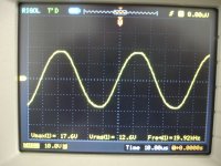
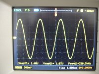
sx amplifier on the test bed.
each set :1st INP. signal
2nd OUT.signal
All scopes,output on a dummy load 7R.
each set :1st INP. signal
2nd OUT.signal
All scopes,output on a dummy load 7R.
Attachments
Last edited:
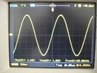
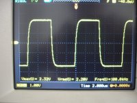
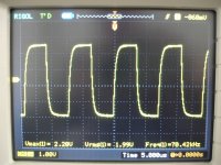
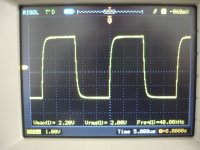
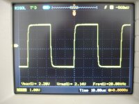
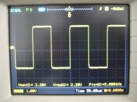
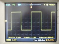
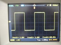
sx amplifier on the test bed.
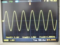
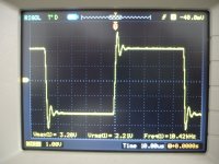
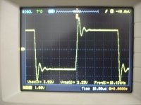
square waves .
I must say that i haven't see flat square waves down to 0.5Hz up to now(first scope 2.9HZ)!
All these on 7R dummy load except last one(100KHz) .This taken before L out.
square waves .
I must say that i haven't see flat square waves down to 0.5Hz up to now(first scope 2.9HZ)!
All these on 7R dummy load except last one(100KHz) .This taken before L out.
Attachments
-
 DSC08061.JPG524.9 KB · Views: 105
 -
 DSC08046.JPG578.3 KB · Views: 101
 -
 DSC08045.JPG545.1 KB · Views: 101
 -
 DSC08042.JPG612.5 KB · Views: 98
 -
 DSC08040.JPG614.7 KB · Views: 94
 -
 DSC08039.JPG522.4 KB · Views: 90
 -
 DSC08037.JPG601.7 KB · Views: 93
 -
 DSC08036.JPG534.6 KB · Views: 97
 -
 DSC08035.JPG522.4 KB · Views: 94
 -
 DSC08034.JPG595.7 KB · Views: 141
Last edited:
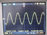
sx amplifier on the test bed.
Amplifier bandwidth .
1)1KHz
2)0.237Hz
3)320KHz.
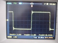
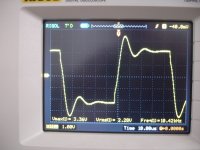
The rest is a stability test.
4)7R//47nf
5)7R//150nf
6)7R//330nf
7)7R//2.2uf
Amplifier bandwidth .
1)1KHz
2)0.237Hz
3)320KHz.
The rest is a stability test.
4)7R//47nf
5)7R//150nf
6)7R//330nf
7)7R//2.2uf
Attachments
Last edited:
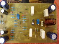
1)unfortunately i haven't good heatsinks.🙁
2)0.5W resistors?Look i have 0.22R /5W non inductive resistors instead of 0.33R/5W (Bias resistors).
BTW This second channel is alive! Just for test with a ridiculous heatsink up to now.🙁
I love the bass of this amplifier (C.F.A with deep&strong bass???).
Best Regards.
Thimios.

When you have these style heatsink turn them 100% face to face and ad to the end a 4x4inch fan or a computer fan what ever will have the right size.
That will triple up your heatsink capacity .
Just as a advise.
😀😀😀😀😀
each set :1st INP. signal
2nd OUT.signal
All scopes,output on a dummy load 7R.
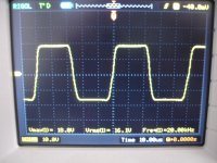
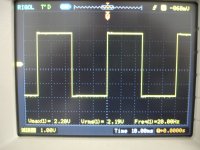
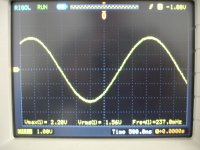
Thimios, the last scope shot in your first set of plots says 20 kHz, but the rise/fall time seems very long. It does not seem right.
I have the same Rigol scope (+ a 200 MHz Philips analog one as well) BTW.
LF square waves will be flat topped with the sx and nx Amp - no servo and no DC blocking caps - all DC coupled. Hiraga's 20 W class A was also like this.
Good to see you have them running ok - we just need to clear up the 20 kHz query.
aaah! I. Just realized that plot is of a sign wave with the amp being hard overdriven - so it's ok! No sticky rail - that's good!
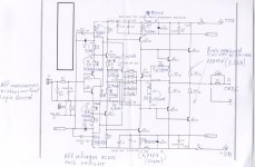
The volt drop you need to measure is across R32 and R33 - should be about 1 V.
Voltages around the circuit look good.
Voltages around the circuit look good.
Last edited:
That's right!aaah! I. Just realized that plot is of a sign wave with the amp being hard overdriven - so it's ok! No sticky rail - that's good!
Is that across the 1k R32 and R33 resistors? You are showing the same voltage across the 15 ohm filter resistors.
Oh no sorry apologize.Is that across the 1k R32 and R33 resistors? You are showing the same voltage across the 15 ohm filter resistors.
777mV is the voltage across 15R filter resistors
I haven't measure these(R32,R33)voltages.I will measure these soon.
Last edited:
The drop across the 15 ohm resistors looks correct.
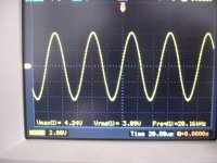
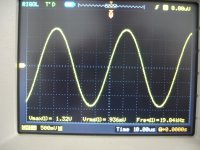
For your stability tests, the reason you see the ringing on the square wave is because the load capacitance is forming a resonant circuit with the output inductor. This is quite normal.
To test the amplifier stability, feed a square wave into the amplifier and check that there is no overshoot before the inductor. From what you have shown anyway, your amp looks stable and good.
Absolutely right!The drop across the 15 ohm resistors looks correct.
For your stability tests, the reason you see the ringing on the square wave is because the load capacitance is forming a resonant circuit with the output inductor. This is quite normal.
To test the amplifier stability, feed a square wave into the amplifier and check that there is no overshoot before the inductor. From what you have shown anyway, your amp looks stable and good.
This amplifier is rock stable without any instability issue,no overshoot or ringing.
The reason that tested with capacitive load is because many guys here asking about this,i see same measurements in your pdf presentation also
Last edited:
V R32=1.2vIs that across the 1k R32 and R33 resistors? You are showing the same voltage across the 15 ohm filter resistors.
V R33=1.2v
Thos voltages are good (the drop is a little higher than the 1Vi mention the in article - but your readings are correct.)
The nx-Amp is also very stable like this as well.
Let's us know how it sounds once you have it set up and running.
The nx-Amp is also very stable like this as well.
Let's us know how it sounds once you have it set up and running.
- Home
- Amplifiers
- Solid State
- SX-Amp and NX-Amp