PSU fully tested and operational! 😀
I have now replaced my test caps with Mundorf M-Lytics 22000uF 63V. Tomorrow I'll start drilling some holes on my test heatsink for calibrating/testing my amp modules!!
Ciao!
Do
I have now replaced my test caps with Mundorf M-Lytics 22000uF 63V. Tomorrow I'll start drilling some holes on my test heatsink for calibrating/testing my amp modules!!
Ciao!
Do
PSU fully tested and operational! 😀
I have now replaced my test caps with Mundorf M-Lytics 22000uF 63V. Tomorrow I'll start drilling some holes on my test heatsink for calibrating/testing my amp modules!!
Ciao!
Do
Great news!!
Looking forward to seeing some pictures!
Soon... I dropped my iPhone today and destroyed the display 😡
I will post pictures once I get a replacement
Ciao!
Do
Do too bad you broke your Iphone but good musical amp will be born soon 🙂
Yeah! For sure! 😀
Looking forward to it
Thanks
Do
Quite a few people are asking me for sx-Amp boards.
I will re- layout the boards for SINGLE SIDED in the next few days and then post them up so you can group buy, or etch your own.
I will re- layout the boards for SINGLE SIDED in the next few days and then post them up so you can group buy, or etch your own.
I just ordered some 150R and 110R resistors to be able to bias the amplifier. I was not getting anything so time to do the mods like on the new schematics! 😀
Hope to get this working early this week and put on some pictures.
Ciao!
Do
Hope to get this working early this week and put on some pictures.
Ciao!
Do
SX amp
This is great news, thanks.
BR,
Eric
Quite a few people are asking me for sx-Amp boards.
I will re- layout the boards for SINGLE SIDED in the next few days and then post them up so you can group buy, or etch your own.
This is great news, thanks.
BR,
Eric
Will you share the gerber files as well?
Terry, yes of course.
Regards
Andrew
Getting there!
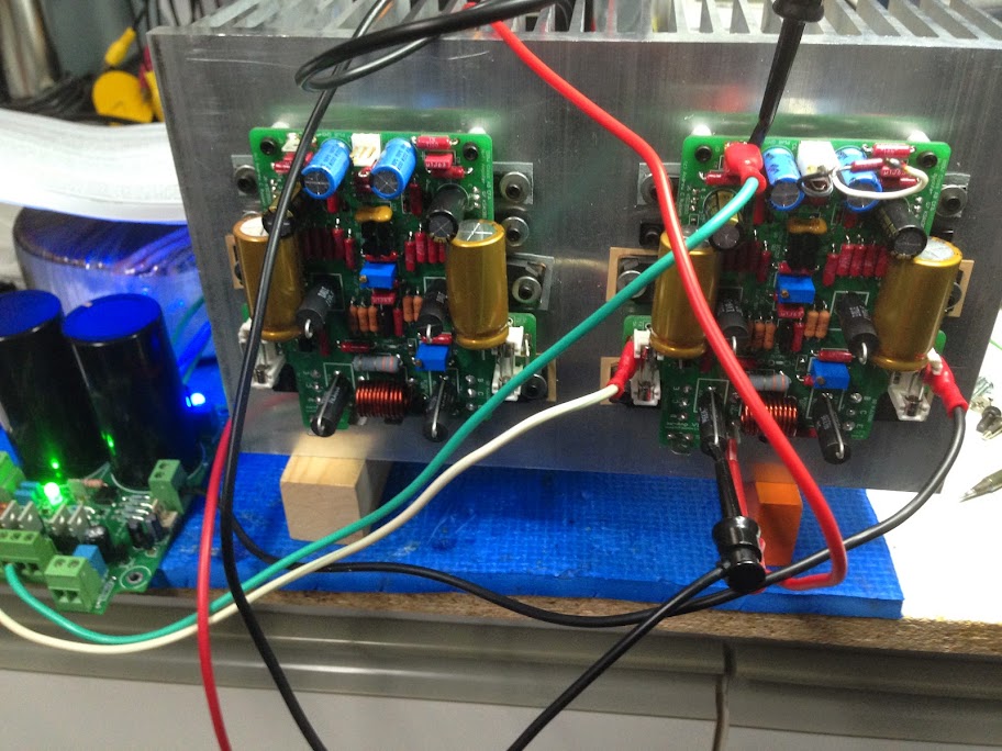
Had to change R28, R29, R36, R37 to 110R and 150R respectively otherwise I could not bias the amplifier. I had missed this update and thanks to Fab I'm back on tracks! 😀
All amps are now fully adjusted but I have not yet tested a signal through them. This will be done in a day or so. Once I know all is fine I will prepare the chassis and the AMB Switch Driver for power up the whole thing.
Getting really excited now!!
Here's the last picture from the test setup
Ciao!
Do
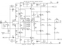
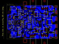
Here is the single sided sx-Amp (15 Watt Class A CFA) PCB layout in Gerber format I promised a few days ago.
I have not built this version (only the THP version)
So, please feel free to take a look.
The circuit is the same as for the one in the write-up on my website except that I have replaced C2 with a through hole electrolytic device and J2 is removed. Further, all the semiconductors are now through hole.
The overlay and circuit diagram are attached as .jpg
NOTE: THIS LAYOUT INCORPORATES THE UPDATED RESISTOR VALUES FOR R28, R29 AND R36 AND R37.
I don't know how to turn this into a .pdf file - anyone got any ideas? This will mean people can etch their own boards.
The write on this amplifier is on my website - here is a link for your convenience: Ovation sx-Amplifier: A 15 W class A Amplifier
Happy building!
Attachments
Last edited:
Bonzai,
at the maximum output of 15W the voltage across the feedback resistors is ~15.5Vac
That gives a dissipation in each of the 5 off 1k0 resistors of ~220mW.
That is very high for a feedback resistor.
Even increasing to 10ff 2k0 resistors gives 110mW. That is double what I would apply to a 600mW feedback resistor.
Have you considered using say 10off 3k resistors to get the maximum dissipation down to a smaller percentage of Pmax for each resistor?
The lower leg would become 22r for similar gain.
Would this higher feedback resistance reduce the amplifier performance?
Last edited:
Andrew,
The feedback resistor is set at 200 Ohms to preserve the SR and BW of this design. The current available to charge the compensation cap in a CFA is related to the value of the feedback resistor and the peak rail voltage.
Re the dissipation, remember the crest factor of music is typically 1:7, lower on modern compressed recordings. So, for music, the total dissipation of the feedback resistors is well within ratings.
I don't know how to turn this into a .pdf file - anyone got any ideas? This will mean people can etch their own boards.
You can install PDFcreator or cutePDF writer and print to file using that drivers.
PDF conversion
Use Nitro Pdf reader. When this is installed, and you choose Print from any program, you get under the option "printer", Nitro PDF Creater. Click print, choose quality settings and where to save and you are done.
Download the free version only. From http://www.nitropdf.com/pdf-reader
Use Nitro Pdf reader. When this is installed, and you choose Print from any program, you get under the option "printer", Nitro PDF Creater. Click print, choose quality settings and where to save and you are done.
Download the free version only. From http://www.nitropdf.com/pdf-reader
Attachments
Last edited:
- Home
- Amplifiers
- Solid State
- SX-Amp and NX-Amp