I've noticed that my protection led does not engage but while powered, if I measure the collector voltage of Q6-Q7 (which is 50V) then while I take the measurement, 4-5 seconds and the protection led turns on...
I did change the PDTA114ET to 144ET and R7 is currently a 16.5K (I omitted the 27K resistor for now)... Should I be using a 20K instead? I did not change C3 0.47uF to 1uF and R6 300K to 100K thinking Bill_P mod was enough?
Thanks
Do
I did change the PDTA114ET to 144ET and R7 is currently a 16.5K (I omitted the 27K resistor for now)... Should I be using a 20K instead? I did not change C3 0.47uF to 1uF and R6 300K to 100K thinking Bill_P mod was enough?
Thanks
Do
I've noticed that my protection led does not engage but while powered, if I measure the collector voltage of Q6-Q7 (which is 50V) then while I take the measurement, 4-5 seconds and the protection led turns on...
I did change the PDTA114ET to 144ET and R7 is currently a 16.5K (I omitted the 27K resistor for now)... Should I be using a 20K instead? I did not change C3 0.47uF to 1uF and R6 300K to 100K thinking Bill_P mod was enough?
Thanks
Do
I'm talking about U1 for PDTA144ET
What is the protection LED you refer to? D15? D16? It appears that your meter input impedance is disturbing the circuit from what you said. What kind of meter are you using?
Do change C3 to 1uF and R6 to 100K. Measure the Q3 drain voltage after power on to be sure that Q3 turns on after a few seconds.
Do change C3 to 1uF and R6 to 100K. Measure the Q3 drain voltage after power on to be sure that Q3 turns on after a few seconds.
What is the protection LED you refer to? D15? D16? It appears that your meter input impedance is disturbing the circuit from what you said. What kind of meter are you using?
Do change C3 to 1uF and R6 to 100K. Measure the Q3 drain voltage after power on to be sure that Q3 turns on after a few seconds.
Yes, it is D15, D16 does not light up
Pinnocchio, please follow the test procedure in the write-up. This will quickly help to isolate the issue.
Also, note that the mods proposed by Bill_P are now included in the document. You can download it from my website.
(I have two nx-Amps running now - one for over a year, and another for about 6 months)
Let us know how it goes.
Also, note that the mods proposed by Bill_P are now included in the document. You can download it from my website.
(I have two nx-Amps running now - one for over a year, and another for about 6 months)
Let us know how it goes.
Hi Bonsai,
I actually was following the test procedure but stopped. Here's what was done:
Changed R6 to 100k
Changed C3 to 1uF
Changed R7 to 18k
Changed U1 to PDTA144ET.256
Changed all LED resistors to 10K
Rail voltage is at 51.5Vdc unloaded
Q6 and Q7 collector voltage both show +50.5Vdc referenced to GND
Q3 show only +0.75Vdc at the Gate referenced to GND
I did not lift R1 since Q6-7 collector voltage was ok
There is no DC at J10 pin 1 & 3 since nothing is connected.
Here's a magnified picture of the under PCB

Here's the top

Thanks
Do
I actually was following the test procedure but stopped. Here's what was done:
Changed R6 to 100k
Changed C3 to 1uF
Changed R7 to 18k
Changed U1 to PDTA144ET.256
Changed all LED resistors to 10K
Rail voltage is at 51.5Vdc unloaded
Q6 and Q7 collector voltage both show +50.5Vdc referenced to GND
Q3 show only +0.75Vdc at the Gate referenced to GND
I did not lift R1 since Q6-7 collector voltage was ok
There is no DC at J10 pin 1 & 3 since nothing is connected.
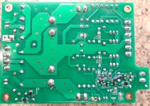
Here's a magnified picture of the under PCB
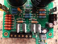
Here's the top
Thanks
Do
Hi Do,
I seem to remember needing to make a trace cut and some resistor changes on the bottom. I used through hole parts because I don't have a supply of SMD parts and didn't want to wait at the time since we were working our way through it. I haven't read the documentation on Andrew's site about the changes for the PSU but I'm pretty sure we had to cut one trace between U1 and Q3 and add a resistor there. Maybe it got changed later, I'm not sure.
My PSU works properly now so I am adding some pics for your use if necessary.
Blessings, Terry
Attachments

Why do you think the voltage at Q6 and Q7 collector is OK? It is below the rail voltage by enough to possibly turn on U3 partially. Measure the voltage across R1 and if it isn't zero then the DC detector is pulling the gate of Q3 down.
Q3 needs more than 0.75V gate voltage to turn on fully. The gate voltage is not simply DC as you would see if you measured with a scope. With low gate voltage on Q3 the LED should be off.
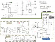
Back when I built my NX I edited the power supply schematic to help me troubleshoot. This version of the schematic is attached in the hope that it helps you as well.
Q3 needs more than 0.75V gate voltage to turn on fully. The gate voltage is not simply DC as you would see if you measured with a scope. With low gate voltage on Q3 the LED should be off.
Back when I built my NX I edited the power supply schematic to help me troubleshoot. This version of the schematic is attached in the hope that it helps you as well.
Attachments
Hi Thierry,
Added the 27K resistor mod that I did omit on purpose but now it is there.
Bill_P,
Thanks to your schematic and careful look, I found the issue! It was U2... I was using PDTA144 instead of PDTC144...😱
All good now! On to the rest of the PSU test! 😀
Ciao!
Do
Added the 27K resistor mod that I did omit on purpose but now it is there.
Bill_P,
Thanks to your schematic and careful look, I found the issue! It was U2... I was using PDTA144 instead of PDTC144...😱
All good now! On to the rest of the PSU test! 😀
Ciao!
Do
is it this type PDTC144ET we need?There are more than ten versions of this trannie
PDTC144ET215
Hi Meanman1964,
See Still4given post #892 & #907 and schematic on #908 for 27k resistor and trace cut.
Mods on #906 (It is PDTA144ET215 for U1, not 256...)
Also download the latest BoM (page 32) and Erratum.
Ciao!
Do
See Still4given post #892 & #907 and schematic on #908 for 27k resistor and trace cut.
Mods on #906 (It is PDTA144ET215 for U1, not 256...)
Also download the latest BoM (page 32) and Erratum.
Ciao!
Do
Last edited:
Where is the 27 K mod going? Is there a trace need to be cut?
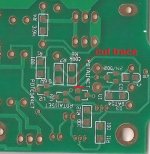
Just one trace needs to be cut. You can see the 27K resistor I added in the pic above. It attaches to U1 and Q3. Easier would be to use an SMD resistor and just scrape a little solder mask off on either side of the cut. I just didn't have any and didn't want to place an order for one or two parts.I'm attaching a pic that shows which trace to cut.
Blessings, Terry
Attachments
I think you're going to like this one. It is a cool build. There is a lot going on in that PSU board withe the protection circuit and everything. I need to get a chassis built for mine. It deserves to be completed.
Blessings, Terry
Blessings, Terry
Excellent. Tell us how it sounds when you are finished!
I know very well how it sounds since I've listened to Fab's build and this is the reason why I'm building it, it sounds really good! 😀
Can't wait to finish it though. I've got the chassis ready for it. I will use the AMB switch driver for power on and overheat protection.
Ciao!
Do
Excellent. Tell us how it sounds when you are finished!
First i've to order some PDTC144ET and smd resistors
- Home
- Amplifiers
- Solid State
- SX-Amp and NX-Amp