Hi Andrew,
Thanks for the file. I have a few questions.
First of all, the spice file schematic is quite a bit different from the nx schematic. Very stripped down and hard to compare because all of the components have different labels.
Next, I didn't have the drivers in my spice library so I had to change them out to KSC3503/KSA1381 to get it to run. Guess what, -580mv offset. I had hoped to be able to tweak things and see if I could duplicate my issues but this file is so different from actual nx that I wouldn't know where to start. I am attaching my file with the different models so maybe you can give some pointers.
Can you tell me what Rdegen means in the resistor value?
Thanks, Terry
Attachments
Rdegen is set to 15 Ohms - it just allows you to change the value of a whole lot of resistors of the4 same value globally.
The model it just there to do basic debugging and optimization (compensation, loop gain, basic DC performance etc).
Every amp I sim has offsets. You have some other issue on your boards Terry because you've measured the node voltages and they are all correct.
BTW, I ordered a set of boards from Stanton - I will take a look at them just to make sure they are ok and there is not some other issues with them.
Yeah, who knows? I have replaced all of the transistors several times. This last time lifted one of the traces on the top of the board. Didn't break it but still not good. Not only has there been no change, but I have been throwing away well matched devices which get harder to come by, the smaller my supply gets. Surely I am not the only one to build this amp on Stanton's boards so I must have something wrong somewhere but just can't find it. I'm going to set this amp aside for a while and work on something else. Your spice file was my last hope but it is so different from this amp that it really doesn't provide the help I had hoped for. Thanks for taking time to try and help me. I'll keep an eye on this thread and maybe someone else will have similar issues and find a solution.
Blessings, Terry
Blessings, Terry
Terry, as discussed via email, please feel free to mail your boards to me - I will be quite happy to take a look at them.
I will assemble one of Stanton's boards and report back on this thread what I find.
Regards
Andrew
I will assemble one of Stanton's boards and report back on this thread what I find.
Regards
Andrew
Sorry, no . . . can you post it again?
Can I use fodm3052nf098 as replacement of FODM3012R2VNF098?
I played around with the spice file. I tried to add the things I could see that were missing. No matter what I try, I can't get rid of the off set. Maybe someone could look over my file and see if they can find the problem. My amp is pretty much doing the same thing as the sim so maybe if we can find a cure there I can find it in my amp.
Thanks, Terry
Thanks, Terry
Attachments
Can I use fodm3052nf098 as replacement of FODM3012R2VNF098?
I took a quick look. Yes this looks like a suitable replacement.
I was suggesting to provide them for those who needed them more quickly than to wait for the distributor to get them...They are OK
Just send me a PM with your address and I will mail 2 of them. The only thing is that you also order them from a distributor and when you get them eventually then ship them to me so I can build another set of NX amp with MOSFET output eventually ....
Fab
Last edited:
I played around with the spice file. I tried to add the things I could see that were missing. No matter what I try, I can't get rid of the off set. Maybe someone could look over my file and see if they can find the problem. My amp is pretty much doing the same thing as the sim so maybe if we can find a cure there I can find it in my amp.
Thanks, Terry
Terry, your file have an error, double C7.
I use transistor model from keantoken. Just sweep the voltage of V3 to find 0V at output.
Attachments
Do you need mine or not?
Yes I do cause I've to wait a month for mine,did send a mail to you
Thanks Bimo, You are tight, I didn't need the second C7. I didn't notice the original and added it. I have taken it out. I don't know how to sweep V3 or even how it compares to the way the amp is actually wired. Can you give a little more instruction?
The file doesn't run in my program. You must have changed something.
Thanks, Terry
The file doesn't run in my program. You must have changed something.
Thanks, Terry
Thanks Bimo, You are tight, I didn't need the second C7. I didn't notice the original and added it. I have taken it out. I don't know how to sweep V3 or even how it compares to the way the amp is actually wired. Can you give a little more instruction?
The file doesn't run in my program. You must have changed something.
Thanks, Terry
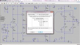
You must use your own transistor model. Your "standard.bjt" file is different than mine. Please see this picture below. Then "Run" ltspice. Click output voltage to see graph V3 vs Output voltage. You can find value of V3 when output voltage is zero.
Attachments
Hi Bimo,
Yes, I had changed back the transistors but when I hit run it just brought up a list and didn't give me the opportunity to read voltages around the schematic. I Don't understand how V3 simulates R3 in the amp circuit.
Yes, I had changed back the transistors but when I hit run it just brought up a list and didn't give me the opportunity to read voltages around the schematic. I Don't understand how V3 simulates R3 in the amp circuit.
Hi Bimo,
Yes, I had changed back the transistors but when I hit run it just brought up a list and didn't give me the opportunity to read voltages around the schematic. I Don't understand how V3 simulates R3 in the amp circuit.
Click "Edit" ->"SPICE Analysis". Click "DC Sweep" input the value on my attachment in my previous post. Or you can write command ".dc V3 -10 10 0.1"
It will make voltage of V3 from -10V to 10V with 0.1V increment.
If you don't still understand please search google about "DC sweep on LTSpice". My english is not good, sorry.
Good news. I sent my spice file to a friend and he said to try piggy-backing a 1k resistor on R1. Worked perfectly. Now I can adjust the offset to 0.0 and all the voltages look symmetrical. Playing music on one of the boards right now. I guess I probably need to cut the jumper on the input and will still need to get the speaker protect part of the PSU board working but at least I have figured out the offset issue.
Thanks for all the help.
Blessings, Terry
Thanks for all the help.
Blessings, Terry
- Home
- Amplifiers
- Solid State
- SX-Amp and NX-Amp