For the coupling cap
You can use an electrolytic of at least 35V (50 preferable) assuming your is running off +- 15 to 18 volts. Make sure it's very oversized though to should LF distortion - so 100 uF would be ok. Nichicon, Panasonic etc are all good.
However, film ( avoid polystyrene if you can) is better, and a 10uF part will do the job. Be aware that the film cap will probably be quite large and expensive. Try Vishay, Wima or Panasonic for this part. A 50 V device will be ok.
Just in case , I was only sarcastic about "the pressure"...😉Looks better fab!
Yes, this is for fun and musical enjoyment!
However, the 10khz square wave on the 8 ohm parallel with 1.2uF with my previous 1uh was better damped...🙁
Fab
Last edited:
Thanks Junie.
I still need some time before enjoying the music...🙁
Finally I could no more support the pressure and changed my inductor by looking in my electronic junk parts...😉
However I could not find 12awg wire...
Fab
Ah you made an Air core inductor already, that will do the job 😀.
If you are measuring after the inductor it will ring - the output inductor and the cap form a resonant circuit. Without the inductor, you still get ringing in a real world situation as the speaker capacitance and cable inductance also form a tank circuit.
If you the amp before the inductor with 8 ohms and test with a square wave, you should get no overshoot ( nothing connected on the inductor output side)
If you the amp before the inductor with 8 ohms and test with a square wave, you should get no overshoot ( nothing connected on the inductor output side)
Has anybody ever reported to Bonsai that Mosfets in SS relay are two times more expensive than output transistors in the amp itself!
If you are measuring after the inductor it will ring - the output inductor and the cap form a resonant circuit. Without the inductor, you still get ringing in a real world situation as the speaker capacitance and cable inductance also form a tank circuit.
If you the amp before the inductor with 8 ohms and test with a square wave, you should get no overshoot ( nothing connected on the inductor output side)
Hi Bonsaï
Ok I will try your test.
Just to ensure I have the same performance as your built NX amp do you have a scope screenshot of a capacitive load test you have done f.or comparison purpose with mine...
Thanks
Fab
Last edited:
Good evening to all 
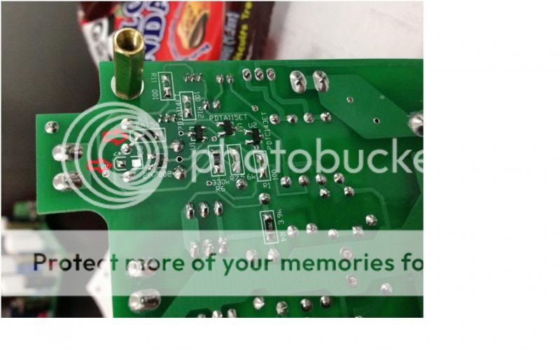
kindly confirm please, from the below photo if the cathode is the side where I pointed the arrows?
kindly confirm please, from the below photo if the cathode is the side where I pointed the arrows?

Hi Bonsaï
Ok I will try your test.
Just to ensure I have the same performance as your built NX amp do you have a scope screenshot of a capacitive load test you have done f.or comparison purpose with mine...
Thanks
Fab
I will have to try to find it fab. But, it's easy to calculate:
Fo = 1/(2*Pi * sqr(Loutput*Cload))
Where Loutput is the output inductor in Henries and Cload is your load capacitance.
I will have to try to find it fab. But, it's easy to calculate:
Fo = 1/(2*Pi * sqr(Loutput*Cload))
Where Loutput is the output inductor in Henries and Cload is your load capacitance.
I mean the amount of damping of this frequency...
Fab
Here are two pictures. The first is what the sim predicted when a high value cap (I believe it was 1uF) was connected after the sx-Amp output inductor across an 8 ohm load and the second is the actual measured ringing. This is a worst case scenario. In practice, the ringing will be much lower than this because most speakers don't have input capacitances of 1 or 2 uF - although electrostatics are sually very high (which is the historial reason for the 2uF//8 Ohm torture test)
Its difficult to predict how much ringing will take place without understanding what the speaker load looks like. The best way to assess this I'd say is to get a speaker LTspice model and then drive it with a sqaure wave source with some inductance (the speaker cable) in series and take a look.
But, you really dont need to know this (i.e. damping) to be able to design an amplifier. The important things to remember that a metre of speaker cable is 'approximately' 1uH, and in a typical installation you will have therefore 3-4 uH of inductance in series with the speaker. Its this inductance and the speaker input capacitance that causes the ringing - not the amplifer being unstable or anything like that. ALL amplifiers driving the kind of load I have just described will show this behaviour.
If you remove the inductor i.e. short it out, or link straight across it on the pcb, all that will happen is the ringing will move up in frequency - the speaker cable and the speaker input capacitance still ring.
Attachments


Last edited:
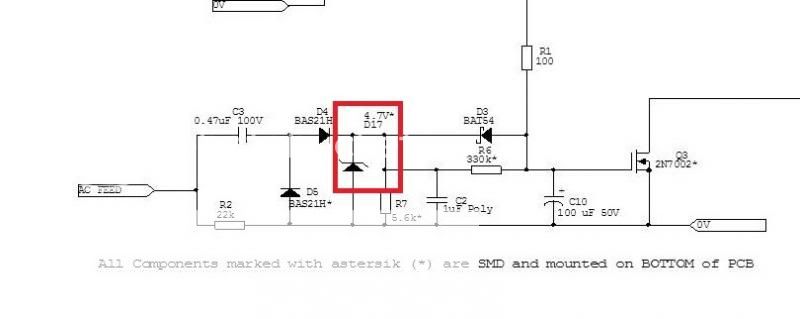
D17
Thanks Andrew.
Good morning Guys!
Andrew how critical is the Value of D17, I forgot to order 4.7v but I can salvage 6.2v from scrap PCB.
BR,
Junie
Yes, where the arrows are is the cathode.
Looks neat Junie!
Thanks Andrew.
Good morning Guys!
Andrew how critical is the Value of D17, I forgot to order 4.7v but I can salvage 6.2v from scrap PCB.

BR,
Junie
If you remove the inductor i.e. short it out, or link straight across it on the pcb, all that will happen is the ringing will move up in frequency - the speaker cable and the speaker input capacitance still ring.
Well worth a read if you're into this sort of thing.
http://www.firstwatt.com/pdf/art_spkr_cable.pdf
If you remove the inductor i.e. short it out, or link straight across it on the pcb, all that will happen is the ringing will move up in frequency - the speaker cable and the speaker input capacitance still ring.
Than we could perhaps put link instead of inductor? Will the amp in that case be unstable with some types of cables like braided Kimber, etc?
Thanks Andrew.
Good morning Guys!
Andrew how critical is the Value of D17, I forgot to order 4.7v but I can salvage 6.2v from scrap PCB.
BR,
Junie
It will work ok, although the reset time might be a bit longer. I'd say, go ahead and use the 6.2V device.
Than we could perhaps put link instead of inductor? Will the amp in that case be unstable with some types of cables like braided Kimber, etc?
You can link the inductor out and try it. For most general dynamic speakers, the sx and nx amp will probably be OK without the inductor. I generally keep PM and GM well above 60 degrees and GM well above 10 dB - usually 15 dB because I don't believe in taking any chances. Both the sx and nx Amps will drive any load without stability problems if the inductor is in place - i.e. unconditionally stable designs.
But, the inductor is easy to wind and it looks cool . . . 😉
Well worth a read if you're into this sort of thing.
http://www.firstwatt.com/pdf/art_spkr_cable.pdf
Nice article - as usual from Nelson, no b.s. and no posturing, just facts and solid engineering.
😎
You can link the inductor out and try it. For most general dynamic speakers, the sx and nx amp will probably be OK without the inductor. I generally keep PM and GM well above 60 degrees and GM well above 10 dB - usually 15 dB because I don't believe in taking any chances. Both the sx and nx Amps will drive any load without stability problems if the inductor is in place - i.e. unconditionally stable designs.
But, the inductor is easy to wind and it looks cool . . . 😉
No doubt, the inductor will be in place!
Here are two pictures. The first is what the sim predicted when a high value cap (I believe it was 1uF) was connected after the sx-Amp output inductor across an 8 ohm load and the second is the actual measured ringing. This is a worst case scenario. In practice, the ringing will be much lower than this because most speakers don't have input capacitances of 1 or 2 uF - although electrostatics are sually very high (which is the historial reason for the 2uF//8 Ohm torture test)
Its difficult to predict how much ringing will take place without understanding what the speaker load looks like. The best way to assess this I'd say is to get a speaker LTspice model and then drive it with a sqaure wave source with some inductance (the speaker cable) in series and take a look.
But, you really dont need to know this (i.e. damping) to be able to design an amplifier. The important things to remember that a metre of speaker cable is 'approximately' 1uH, and in a typical installation you will have therefore 3-4 uH of inductance in series with the speaker. Its this inductance and the speaker input capacitance that causes the ringing - not the amplifer being unstable or anything like that. ALL amplifiers driving the kind of load I have just described will show this behaviour.
If you remove the inductor i.e. short it out, or link straight across it on the pcb, all that will happen is the ringing will move up in frequency - the speaker cable and the speaker input capacitance still ring.
Hi Bonsaï
When I connect the 1uf cap at the 8 ohms load which is connected at about 6 inches wire length from the amp speaker terminal then I get a similar waveform as yours.
Fab
- Home
- Amplifiers
- Solid State
- SX-Amp and NX-Amp