Power amp ....completion...
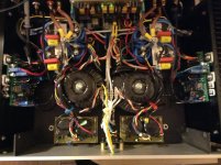
I have used a previous DIY amp project and replaced the amp boards with the NX ones... However I have not used the. NX associated PS board since I already had a power supply. The only thing that s still bothering me is the lack of over current protection (as in the NX PS board) in case I do a short at the speaker terminal... 🙄
I intend to use the triac on the NX amp board eventually ...
Fab
Attachments
Hi Bonsaï
When I connect the 1uf cap at the 8 ohms load which is connected at about 6 inches wire length from the amp speaker terminal then I get a similar waveform as yours.
Fab
Thats correct - the cap is ringing with the output inductor and this is quite normal.
I have used a previous DIY amp project and replaced the amp boards with the NX ones... However I have not used the. NX associated PS board since I already had a power supply. The only thing that s still bothering me is the lack of over current protection (as in the NX PS board) in case I do a short at the speaker terminal... 🙄
I intend to use the triac on the NX amp board eventually ...
Fab
Wow - those nx-Amps look lost in there! Looks pretty compact - how does it sound?
Wow - those nx-Amps look lost in there! Looks pretty compact - how does it sound?
It is a dual mono amp configuration so this why it looks so crowdy...
Still no sound test yet b/c first its too late and my wife is asleep and second since I had no 10uf film cap I have used 3.3uf but now realize that I should probably change the 10k input resistor to 47k to prevent low frequency phase shift...🙄
Or should I simply remove the 10k resistor ?
Fab
Last edited:
Fab, you cannot remove the 10k resistor - and I would not recommend you change it to 47k either.
If you use the 3.3uF, the - 3dB point will be about 5 Hz versus c. 1.5 Hz with the 10uF.
I think for testing you can go with the 3.3 uF, but I'd put a 10 uF film cap in there when you can get one.
If you use the 3.3uF, the - 3dB point will be about 5 Hz versus c. 1.5 Hz with the 10uF.
I think for testing you can go with the 3.3 uF, but I'd put a 10 uF film cap in there when you can get one.
Fab, you cannot remove the 10k resistor - and I would not recommend you change it to 47k either.
If you use the 3.3uF, the - 3dB point will be about 5 Hz versus c. 1.5 Hz with the 10uF.
I think for testing you can go with the 3.3 uF, but I'd put a 10 uF film cap in there when you can get one.
For the input resistor , is it for lower noise and DC offset reduction since the 100k resistor is already at the base of input transistors? But there is already a pot to correct DC offset...
A lot of other amps do not have this added input resistor or it is a higher value like 100k😕
Should I use 47uF electrolytic bipolar cap like Nichicon muse (which I have in stock ) instead of my 3.3uf film cap without changing any resistor?
Fab
Fab, ignore the 100k resistor for now. Indeed, you can take it out if you like. You cannot however change the 10k resistor - this is where the input transistor bias currents come from and it sets the input resistance of the amp.
If you have. 47 uF cap, thats good and certainly will give your amp LF extension to well below 1 Hz. There is a lot of debate around the audibility of capacitors, and especially electrolytics. Self has no problem with them, RC and JC feel differently. I'd try both and see which you prefer.
The cap should fit from the 10k resistor to the output of your preamp.
Last edited:
Fab, ignore the 100k resistor for now. Indeed, you can take it out if you like. You cannot however change the 10k resistor - this is where the input transistor bias currents come from and it sets the input resistance of the amp.
If you have. 47 uF cap, thats good and certainly will give your amp LF extension to well below 1 Hz. There is a lot of debate around the audibility of capacitors, and especially electrolytics. Self has no problem with them, RC and JC feel differently. I'd try both and see which you prefer.
The cap should fit from the 10k resistor to the output of your preamp.
I would try the combination of BiPolar with film bypass for the best of both worlds -- extension and clarity at low and high ends of the spectrum.
However, if using one OR the other, i would opt for the film, only.
Thx-RNMarsh
Fab, ignore the 100k resistor for now. Indeed, you can take it out if you like. You cannot however change the 10k resistor - this is where the input transistor bias currents come from and it sets the input resistance of the amp.
If you have. 47 uF cap, thats good and certainly will give your amp LF extension to well below 1 Hz. There is a lot of debate around the audibility of capacitors, and especially electrolytics. Self has no problem with them, RC and JC feel differently. I'd try both and see which you prefer.
The cap should fit from the 10k resistor to the output of your preamp.
I am interested in a bit more information on the input network. Under quiescent DC conditions what is the base current in Q8 and Q10? What is the DC voltage across R10, the 10K resistor at the input? If you have a LTspice schematic file for the amplifier would you post it here?
I would try the combination of BiPolar with film bypass for the best of both worlds -- extension and clarity at low and high ends of the spectrum.
However, if using one OR the other, i would opt for the film, only.
Thx-RNMarsh
Ok, I changed the 3.3uf film cap to 47uF bipolar Nichicon Muse in // with 0.47uF MKT type cap.
Fab
I am interested in a bit more information on the input network. Under quiescent DC conditions what is the base current in Q8 and Q10? What is the DC voltage across R10, the 10K resistor at the input? If you have a LTspice schematic file for the amplifier would you post it here?
Bill, I'll post it up tonight.
The emitter current of the two input buffer transistors is set at around 1mA and the transistor gains are typically 500 or so (BC547C and 557C). Some portion of the bias current flows between the bases of the transistors - a bias cancelling effect - and the rest is provided by the 10k input resistor. So, the maximum bias current you are likely to see in practice flowing through the 10k resistor is somwhat below 2uA, giving a worst case input offset of about 20mV (I am talking here about an offset caused by input bias current only and not any arising from Vbe mismatches). In practice its going to be much lower than this due to the cancelling effect I already mentioned.
Note that the 100k resistor is actually not needed - it is a place holder from when I was considering making the input AC coupled. I will probably mod the layout to provide this facility, but for now, its DC coupled.
I would try the combination of BiPolar with film bypass for the best of both worlds -- extension and clarity at low and high ends of the spectrum.
However, if using one OR the other, i would opt for the film, only.
Thx-RNMarsh
Good advice Richard! I have the link to your original capacitor selection article (the one you wrote with Walt Jung) posted up on my website - my recomendation is that everyone reads it.
Picking Capacitors - Walter G. Jung and Richard Marsh
Here are all the document updates that need to be done - I've just captured them as the points have come in. Any others, please add them. I will start the update process once I get a few reports in about completed working amplifiers
1. Correct circuit –Q9 and Q11 – cannot use BC547 and BC557 devices – their max Vceo is 45V. Use BC546 and BC556 because their Vceo is 65V; OK to use ‘B’ devices
2. Also ok to use lower gain grade devices for TIS transistors KSC3503 and KSA1381 but must be the same gain grade
3. Comment on TIS current – sim’d and measured difference and why this is so - check TIS current – doc says 25mA, sims say 28mA measured is 43mA
5. Talk about option to increase TIS emitter resistors to say 22 or 27 Ohms
6. Check front end buffer load resistors – 4.7k or 10k? has big impact on TIS current
7. Add coil winding details: 8 turns of 2mm thick solid copper wire on 10mm former. Total outside diameter of coil is 14.25mm and total length is 17mm. Add photo as well.
8. Add transistor pin-out diagram page.
9. Correct supply voltage shown on circuit diagram – says +-20V - must say +-50 V maximum
10. Slew rate and small signal rise time numbers - you did not differentiate these two terms clearly in the doc.
11. Discuss Loop compensation - Add a section to cover this with original LTspice plots
12. Clean up main filter capacitor spec in document: 22mfd 50V (remove reference to 47mfd device)
13. Correct circuit diagram of protection circuit – R15 and R16 are 100k (shown as 22k on circuit. Note PCB is correct)
14. Tighten up description of transformer secondary voltage vs load spec. 34-0-34 at 5% regulation will give 49V
15. Check and correct BOM lists following on from above points.
16. Add points and plots to show that the nx-amp input stage does NOT go into class B
17. Change the output transistor holes to 1.6mm on the PCB’s
18. Move the 2.7k logos on the feedback resistors – they are need to be centralized within the resistor ouline
19. Check PSU main capacitor holes – make them a bit bigger
20. Cover capacitive coupling the input and how to do it.
21. Update PCB to remove 100k resistor on input - not needed
22. Check BOM list
23. Propose alternative transistors for the drivers
Last edited:
23. Propose alternative transistors for the drivers
Look no further:
KSA1220A/KSC2690A
cheap, easily available from mainstream distributors, good specs for drivers, available at the same (high) hfe, isolated case for easy assembly
Used as drivers in NAD C315BEE (Current feedback) amp, form Sziklai CFP outputs, so now I know that it is possible to use Sziklai output stages in CFB amps!
Last edited:
Look no further:
KSA1220A/KSC2690A
cheap, easily available from mainstream distributors, good specs for drivers, available at the same (high) hfe, isolated case for easy assembly
Used as drivers in NAD C315BEE (Current feedback) amp, form Sziklai CFP outputs, so now I know that it is possible to use Sziklai output stages in CFB amps!
got it - willl add these!
I'm testing the NX amp and was impressed  .
.
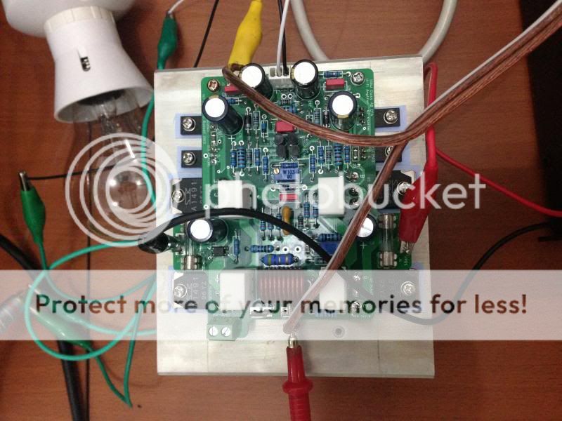
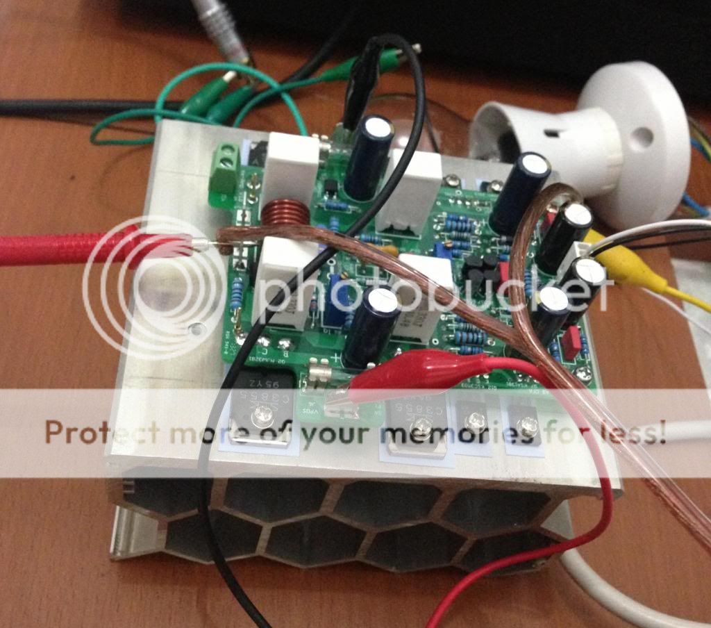
BIG thanks to Andrew, Peter and everyone who contributed. This is the BEST amp anyone should build, you guys won't regret it.
.

BIG thanks to Andrew, Peter and everyone who contributed. This is the BEST amp anyone should build, you guys won't regret it.
I'm testing the NX amp and was impressed
BIG thanks to Andrew, Peter and everyone who contributed. This is the BEST amp anyone should build, you guys won't regret it.
Hi Junie
Have you tested electrically only or listened to it also?
Mine is playing in my living room since last Thursday! I wanted to do some serious listenings before posting here. The main reason for that is that I am using an electrolytic cap for input coupling and I wanted some burn-in ...(even though it is bypassed by a film cap...). Also, I am also performing burn-in at the same time on new DIY speakers so I have lost some references for comparison purpose...
However I can say at this moment that the NX amp:
1) has a great soundstage. From memory in the same level as my Hiraga super class A and my VSSA type amps where it is very good. These 3 amps are all current feedback type.
2) has great dynamics and a solid bass.
3) very clean sound with no exaggerated sibilance.
When I have the chance to compare with my other amps I will keep you posted.
But in general, I personally like this amp so far

Thanks Bonsai and PMI
Nice heatsink by the way Junie ... it seems to be perfect for the bees....
Fab
....
The emitter current of the two input buffer transistors is set at around 1mA and the transistor gains are typically 500 or so (BC547C and 557C)...
Just for general information, (or amusement, not sure which):
BC546B/556B I have from Mouser have hfe around 330-350
BC546C/556C, old stock from Bob Ellis, 420-520
BC556C, samples from Dominic, sourced in Europe, 640-660
BC550C/560C from Mouser, 600-680
VAS:
KSC3503E/KSA1381E , heatsinked, tested as random pairs
(The KSC3503E is old stock, the KSA1381E is new, from Mouser)
(pair 1, good match)
12mA:
hfe: 190/172
Vbe: .645/.652
Vce: ~27V
18mA:
hfe: 205/193
Vbe: .620/.623
Vce: ~37V
(pair 2, fair-to-poor match)
12mA:
hfe:192/160
Vbe: .637/.645
18mA:
hfe:200/172
Vbe: .629/.634
- Home
- Amplifiers
- Solid State
- SX-Amp and NX-Amp