I think I got it!
Q6, Q7 (VAS) should be as specified KSA1381/KSC3503 and well matched if possible.
Q12, Q13 (drivers) does not have to be high spec like KSA/KSC pair and does not have to be well matched (but won't hurt if they are high spec and well matched)
Q1, Q2, Q4, Q5 (output transistors) does not have to be well matched because there are 0R33 emiter resisitors (and matching them would require huge quantity and hence a lot of money)
Ivanlukic,
You are correct. These points will be covered in the updated write up.
Ok thanks for the update Ivan and Andrew.
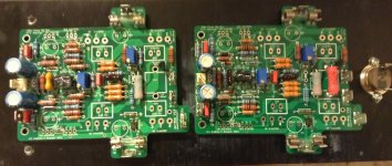
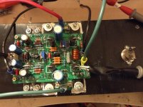
Please see below photo of my progress, I populated the boards with the parts available in my shelf. I will be receiving other parts from Farnell by next week and will do testing soon.

Looks good so far... 😀Ok thanks for the update Ivan and Andrew.
Please see below photo of my progress, I populated the boards with the parts available in my shelf. I will be receiving other parts from Farnell by next week and will do testing soon.
I'm working on assembling the PSU card and found two minor mechanical issues. For C10, 100uF 50V, the component lead spacing is 3.5mm but the board hole spacing is 5mm so the leads must be formed to fit. For J10 the Phoenix connector I bought has three plastic locator tabs intended to go into holes in the board. There are no holes in the board for the tabs so I cut them off. The connector I bought is Phoenix 1725669 - can anyone confirm if this is the right part?
Attachments
I came up with the same part, at least on Mouser. Don't think that is the correct part. The footprint for that connector has six holes, one set for the leads, a second set for the plastic tabs. The plastic tabs are intended to hold the terminal block steady while torque is applied to the screw. Without them, the connector has a tendency to twist. I have other connectors without the tabs. I have not looked at the lead spacing on C10.I'm working on assembling the PSU card and found two minor mechanical issues. For C10, 100uF 50V, the component lead spacing is 3.5mm but the board hole spacing is 5mm so the leads must be formed to fit. For J10 the Phoenix connector I bought has three plastic locator tabs intended to go into holes in the board. There are no holes in the board for the tabs so I cut them off. The connector I bought is Phoenix 1725669 - can anyone confirm if this is the right part?
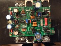
This is my progress on the amp boards...
I still do not have the Power supply/protection board in my hands. However, for the initial test I will use a previous amp with power supply...
Fab
Nice work!
Eventually i'll start mine as well... Just have too many projects for the moment but I'll get there! Good thing is that you will most likely bring it to my home for a good listening session! 😀
Ciao!
Do
Thanks Bonsai!
Finally I decided to use the following drivers (between VAS and output):
2sb1086a-Q/2sd1563a-Q
These transistors purpose is for low frequency audio amplifier driver stage and their HFE is constant up to 300ma compared to about 30ma for the ksa1831/ksc3503. Also, I am able to get 190 HFE for sb/sd type compared to about 145 for the KS type from the stock I have. I understand that Bonsai gave its blessing for that then it should respect the idea of its design....
Also for the output I have selected the best match ( they are from the same lot nimber) for VBE and was able to get 0.486 v for both NPN and 0.484 for both PNP. I am using 1% tolerance 0.30 ohm from the same lot number for RE.
Fab
Last edited:
I m not very good for applying thermal grease with mica insulator ...
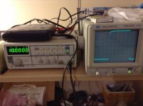
But closer to perform first smoke test...
Fab
But closer to perform first smoke test...
Fab
Attachments
Last edited:

Attachments
Last edited:
Fantastic!
We're you able to dial out the offset ok and set the quiescent current easily?
Lets know how it sounds.
🙂
We're you able to dial out the offset ok and set the quiescent current easily?
Lets know how it sounds.
🙂
Fantastic!
We're you able to dial out the offset ok and set the quiescent current easily?
Lets know how it sounds.
🙂
The DC offset can be adjusted easily with input shorted. However, I need to use DC offset feature of my function generator so the DC stay the same (zero). That brings me the concern if the pre-amp has a small DC component then it is amplified by the power amp by its gain (no feedback cap)... Normally I use a coupling input cap to prevent that Dc but the input cap selection generally affects the overall sound ...
The quiescent current can be easily adjusted too but I am just trying to experiment and I still do not know if it is stable (temp compensation) after a while ( it was late yesterday...).
For the sound it will take a while since I only have one heatsink at this moment....
Also since I have not started your power supply and I entend to use another of mine I need to connect the NX amp over current protection to my existing other pcb DC protect circuit .... I think I have found a way but will require your blessing if you do not mind...
Thanks Bonsai to share your design with us.
Fab
Attachments
Last edited:
The DC offset can be adjusted easily with input shorted. However, I need to use DC offset feature of my function generator so the DC stay the same (zero). That brings me the concern if the pre-amp has a small DC component then it is amplified by the power amp by its gain (no feedback cap)... Normally I use a coupling input cap to prevent that Dc but the input cap selection generally affects the overall sound ...
Fab
I just realized after a good night sleep that we can not short the input w/o a coupling cap to check the noise level otherwise it changes the DC impedance of input stage...

fab
You will need to use a coupling cap between the preamp and the nx-Amp if your preamp has an offset.
To adjust the offset, yes, leave it open circuit.
BTW, what are you using for the output inductor? It should be air cored (not with any type of ferrite).
To adjust the offset, yes, leave it open circuit.
BTW, what are you using for the output inductor? It should be air cored (not with any type of ferrite).
You will need to use a coupling cap between the preamp and the nx-Amp if your preamp has an offset.
To adjust the offset, yes, leave it open circuit.
BTW, what are you using for the output inductor? It should be air cored (not with any type of ferrite).
What coupling cap do you recommend (to not degrade the overall performance). I do have in stock Clarity cap ESA 3.3uf.
Here is the inductor I use (for now):
http://www.mouser.com/ds/2/427/ihd-239901.pdf
Fab
You should replace the inductor with an air core part wound with #12 wire when you finalize the amplifier build.
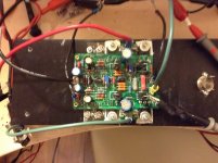
It works!
Fab
Nice one Fab, I'm still waiting for the other parts. Let us know how it sound 😉
Nice one Fab, I'm still waiting for the other parts. Let us know how it sound 😉
Thanks Junie.
I still need some time before enjoying the music...🙁
Finally I could no more support the pressure and changed my inductor by looking in my electronic junk parts...😉
However I could not find 12awg wire...
Fab
Attachments

- Home
- Amplifiers
- Solid State
- SX-Amp and NX-Amp