Bimo,
I took a quick look.
These transistors are very good - there is no reason why they should not work in a practical amplifier.
I think the problem is either with your models or with your circuit.
NOTE: the pin outs are different to the BCxxx types that I used, so make sure you take note of this in your PCB layout.
I've got mine on the bench now.
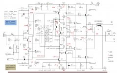
I've taken readings across the bias spreader wrt 0V and am getting +1.295 and -1.285. 1.05 and 1.1 across R31 and R32 and 10.1 across each of the Zeners.
Are you using a bench supply or the actual PSU you will use in the final amp?
Lets take this step by step.
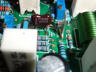
1. Double check C7 - should 68 pF. The marking is probably 680 if it's a silver mica (681 if it's 680 pF)
2. If that's ok, let's focus on looking at the bias issue you have. Lift R1 (10k). This way we can then take DC readings without the offset adjustment masking the errors. Can you then take the measurements you did the other day
Hi Andrew,
OK I double checked C7, it is 68pf see pic.
I lifted R1. Offset is now-800mv
I took measurements based on your voltage chart and have notated them on a new schematic. see below.
Double checked base stoppers and all are in good shape.
I don't have a bench supply. I use a variac and a light bulb circuit for initial start up and then once I'm sure I'm not pulling too much current I hook up direct. I am using the power supply that you designed. Only hooking up to two rails and the ground for testing.
Thanks, Terry
Attachments
Still4Given,
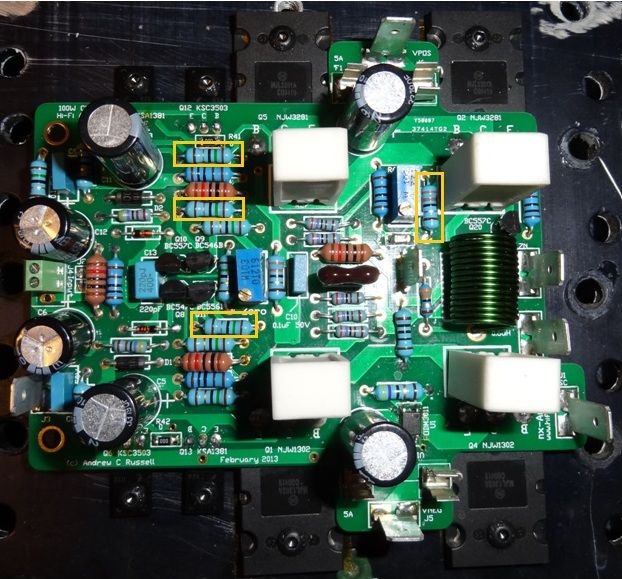
I can see the problem now, that green coiled inductor, should have been red and that brown resistor, they are just clashing. Just joking. The quality of your board work looks very nice, I hope with Bonsai's help you figure this out, I am sure you will. Good luck from another Cali resident.
I can see the problem now, that green coiled inductor, should have been red and that brown resistor, they are just clashing. Just joking. The quality of your board work looks very nice, I hope with Bonsai's help you figure this out, I am sure you will. Good luck from another Cali resident.
Still4Given,
I can see the problem now, that green coiled inductor, should have been red and that brown resistor, they are just clashing. Just joking. The quality of your board work looks very nice, I hope with Bonsai's help you figure this out, I am sure you will. Good luck from another Cali resident.
You are funny 😀. I found it is much difficult to design CFA than VFA. In my first CFA, I burn 2 feedback resistors. May be I do not familiar with CFA. But right now I can made my CFA singing.
I hope I can learn much more from Bonsai.
Your voltages look ok at this point.
If you reconnect R1 and dial the offset out you should be good to go.
If you still have problems after this, we will have to look at the output and driver devices.
There is still the possibility that you have oscillation, but I doing think so.
If you reconnect R1 and dial the offset out you should be good to go.
If you still have problems after this, we will have to look at the output and driver devices.
There is still the possibility that you have oscillation, but I doing think so.
Last edited:
I have built 4 VSSA but they are all mosfet. I wanted to try one with BJT and this looked like a very good one. Still hoping to get it sorted out.
Still4Given,
I can see the problem now, that green coiled inductor, should have been red and that brown resistor, they are just clashing. Just joking. The quality of your board work looks very nice, I hope with Bonsai's help you figure this out, I am sure you will. Good luck from another Cali resident.
LOL!
Your voltages look ok at this point.
If you reconnect R1 and dial the offset out you should be good to go.
If you still have problems after this, we will have to look at the output and driver devices.
There is still the possibility that you have oscillation, but I doing think so.
No they are still way off. Base voltage on the + outputs is only .4V and on the - outputs it is -1.4V. Bias still jumps high when touching the base of Q7 with my test probe. The closest I can get the offset with R1 connected is -340mv.
Thanks, Terry
Hi Terry,
From what I can see here, the multiplier of the highlighted resistors are silver not gold or is it the light only hence wrong value.
From what I can see here, the multiplier of the highlighted resistors are silver not gold or is it the light only hence wrong value.

Can you connect a scope to the output and take a pic without touching anything and then a second pic touching a point in the circuit when the bias jumps. Lets see if this thing is oscillating.
I am not sure about the resistors Junie has pointed out (I also cannot determine the color accurately on my monitor) , but I'd check them again.
Can you confirm that both boards are showing the same problem?
Another thing to try is to monitor the quiescent current and then apply some pressure on the board with a screw driver or meter lead - I am wondering if one of the barrels on the PCB is missing.
Can you check that you do not have a short from any of the device collectors to the heatsink - I cannot see your insulating washers.
Hi Andrew,Can you connect a scope to the output and take a pic without touching anything and then a second pic touching a point in the circuit when the bias jumps. Lets see if this thing is oscillating.
I am not sure about the resistors Junie has pointed out (I also cannot determine the color accurately on my monitor) , but I'd check them again.
Can you confirm that both boards are showing the same problem?
Another thing to try is to monitor the quiescent current and then apply some pressure on the board with a screw driver or meter lead - I am wondering if one of the barrels on the PCB is missing.
I can connect the scope and take a pic but it is just a straight line. Initially, the line jumps off the screen when you first touch the probe but then it settles back onto the screen as the bias settles at 1200mA.
I have measured the resistor several times now, hoping it could be something that simple but they are all correct. The metallic band is gold colored.
Both boards are doing the same thing. My plan was to concentrate on one and then hopefully use what is learned to fix the second.
I use kapton tape for insulation. No grease yet because I have had to remove the boards from the heatsink numerous times in this effort and I don't want the mess. Once everything is good I will apply grease. I check for shorts every time I reinstall.
I'm still not good at understanding how the current and voltage works together across the circuit. I was hopeful one of you who does would be able to look at the voltages I've listed and see were it is going awry.
I'll try to make a more complete schematic later today.
Thanks, Terry
Terry, can you measure at the collector of Q7 wrt GND - thus is the top side driver base voltage.
I just shorted Q12. Smoked some resistors and took out Q6,7,12 &13. I replaced those and now can't adjust the bias so I guess it went deeper than that. I set it aside and grabbed the other board. On that board, Q7 collector is .440V and Q6 is 2.0V. I feel like I'm in the circus.
Hi Andrew,
Q7 collector measures +.987V to ground. Q6 collector measures -1.619V to ground.
Is this with R1 still lifted?
One other thing, can you measure Ohms from the junction of R28 and R29 to GND - should be 15 Ohms.
Reason why I'm asking this is that if this thing was running open loop, or at very high gain, you could see some of the symptoms you are seeing now as well.
If you measure from the output to the junction of R28 and R29 you should get 540 Ohms.
When you measure these, dont just measure across the resistors but from the tracks - if the boards are damaged (i.e. made with a fault) you will be able to pick this up.
- Home
- Amplifiers
- Solid State
- SX-Amp and NX-Amp